








100 Ohm Resistor: Complete Guide to Value, Color Code, and Uses
The 100 Ohm resistor is one of the most used passive components in electronic circuits. But to choose and make a decision as to which one is appropriate is not as straightforward as it seems. From reading color bands and SMD markings, to selecting the correct power rating and tolerance, the smallest of details can have a major impact on the performance and reliability of your circuit. Knowing the properties of a 100 Ohm resistor will help you make better informed engineering decisions while developing a prototype, troubleshooting a PCB or selecting parts for production. But in a practical design the performance of that resistor is influenced by more than just its resistance value. The package type, material and intended application are all factors. This manual contains all the information you need. You will learn how to identify a 100 Ohm resistor and decode its color code, understand its specs, calculate electrical parameters and explore popular applications, and how to choose the correct resistor for your PCB and electronics projects.
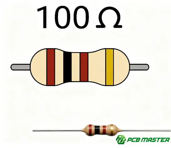
What Is a 100 Ohm Resistor?
100Ω Resistor An electrical component with a resistance of 100 ohms ( 100Ω ). Current management: Improved voltage dip, safety for sensitive components and stability of electrical circuits.
Definition of a 100 Ohm Resistor
A resistor with a resistance of 100 ohms ( Ω ) is called a 100 Ohm resistor . The symbol for ohms is “Ω”. Ohm is a unit of resistance. It is named after the German physicist Georg Simon Ohm. Resistance is how much a substance resists the flow of electric current. Lower resistance resistor goes through with a Higher curren.
The 100Ω resistor and that is restricting the current. Resistor is a device which is used to give resistance to a circuit . This limits the power that could be delivered to other places. This protects LEDs, ICs, sensors or other sensitive components from being damaged by overcurrent. The resistor causes a voltage drop . This can be used to set voltage levels in a circuit .
One of the most common resistor values available is 100 Ohm, an internationally defined E-series resistor value. Good balance of voltage regulation and current limiting. It is widely utilized by engineers in power circuits, signal lines, PCB designs, embedded systems and electronic prototypes. The latter is used in consumer and industrial electronics because of its availability and flexibility.
How a 100 Ohm Resistor Works
100 Ohm resistor will stop electric current. Ohm’s law The current is a function of the applied voltage and resistance
Ohm's Law describes the link between voltage ( V ) , resistance ( R ) and current ( I ) .
Current (I) = Voltage (V) ÷ Resistance (R)
This means that the greater the resistance for a given voltage the less the current. So a 100 Ohm resistor is utilized for dual purpose to limit the current in safe range and also assists to increase the stability of the circuit.
Suppose you have a 5V supply and you want to hook it up to a 100ohm resistor. Ohm's law states:
- Voltage = 5V
- Resistance = 100Ω
- Current = 5 ÷ 100 = 0.05A (50mA)
The resistor is limiting current to 50mA. This stops too much current flowing through the circuit.
Resistor ( 100 Ohm ) to control current / voltage drop . This property is utilized by designers in voltage divider circuits, signal conditioning, pull up and pull down networks and input protection circuits. Therefore, the resistor is extremely important for the safe and reliable operation of electronic equipment under different electrical conditions.
Where Is a 100 Ohm Resistor Used?
100 Ohm is a common part in consumer electronics, industrial equipment, automotive systems and PCB assembly. The latter can be utilized for current control and signalling.
Some typical uses:
- Consumer electronics: LED current limiting, button circuits, audio equipment, changers, smart home appliances, small appliances
- Industrial Control Systems: PLCs, sensors, motor controllers, measurement equipment and industrial automation systems where current reliability and signal integrity is critical.
- Automotive Electronics: Reliable operation of dashboards, lighting modules, engine control units (ECUs), communication networks and other electronic control circuits.
- PCB assembly and embedded systems: Frequently used in printed circuit boards for current limiting, impedance matching, pull up and pull down resistors, signal conditioning and interface protection between microcontrollers and peripheral devices.
For a simple LED indication circuit you can put in 100 Ohm resistor to limit the current via the LED. This prevents the LED from overheating and increases the life cycle of the LED. On a PCB containing a microcontroller the same resistor can be used for an input pin and an output pin. This will restrict the present surge that is noticed during switching events. In these practical applications 100 Ohm resistor is still one of the most specified resistor values in modern electrical and PCB designs.

How Can You Identify a 100 Ohm Resistor?
You can identify a 100 Ohm resistor by its color bands, SMD labeling code or by measuring its resistance with a digital multimeter. How you identify a resistor varies depending on whether it's a through-hole or a surface mount part.
4- Band 100 Ohm Resistor Color Code
The usual color coding for a 4-band 100 Ohm resistor is brown-black-brown-gold. Each colour symbolizes a certain value:
| Band | Color | Meaning |
|---|---|---|
| 1st | Brown | 1 |
| 2nd | Black | 0 |
| 3rd | Brown | ×10 multiplier |
| 4th | Gold | ±5% tolerance |
The first two bands from left to right form the number 10 and third band is a multiplication factor of 10 producing a resistance value of 100Ω. The gold band shows that the actual value of the resistor may vary by ±5%.
The first thing to do when reading a resistor is to find the gold tolerance band. It is normally placed a little further from the other bands. Then read the other bands on the other side. For example, a Brown-Black-Brown-Gold always means a 100 Ohm resistor. If you reverse the order you get an invalid value.
5- Band 100 Ohm Resistor Color Code
The color coding for the 5 band 100 Ohm resistor is Brown-Black-Black-Black-Brown. The extra significant digit is provided by the additional band for a 4-band resistor, thereby providing a higher measurement accuracy.
| Band | Color | Meaning |
|---|---|---|
| 1st | Brown | 1 |
| 2nd | Black | 0 |
| 3rd | Black | 0 |
| 4th | Black | ×1 multiplier |
| 5th | Brown | ±1% tolerance |
The first 3 bands make 100 and the 4th band is a multiplier of 1 . So the value is 100Ω . The brown tolerance band is for ±1% precision so this resistor is suited for applications that demand more exact resistance values.
Industrial electronics, precision measuring equipment, communication devices, automotive electronics, and high-performance PCB assembly often utilize five-band resistors. They are preferred where tighter tolerance helps enhance circuit precision and long term stability.
SMD 100 Ohm Resistor Marking Codes
SMD ( Surface-Mount Device ) resistors, on the other hand, have printed numeric codes rather than colored bands, as in through-hole resistors .
The most frequent 100 Ohm SMD resistor code is:
- 101 (3 digit code)
The first two digits in this system are 10 and the last digit tells you to add one zero. So:
10 x 101 = 100Ω
Some precision SMD resistors have a four digit code:
- 1000
In this case, the first three digits are 100 and the last digit is the multiplier. The multiplier is 0 thus the resistance is still 100Ω.
SMD resistor 100 Ohm available in several package sizes like:
- 0201 – Ultra small portables
- 0402 – Wearables and smartphones
- 0603 — Consumer electronics & embedded systems
- 0805 – Complete PCB Assembly
- 1206 – Higher power uses
Generally the bigger the package size the more heat the resistor can dissipate and the higher the power rating it can tolerate.
How to Verify the Resistance Value
The best approach to check a 100 Ohm resistor is to measure using a digital multimeter, and see whether it matches the marks on the resistor, and the tolerance.
Below are 4 simple steps to check the resistance value:
- If possible, disconnect the circuit or pull the resistor off the PCB.
- Set the digital multimeter in the resistance (Ω) mode.
- Put the test probes on both ends of the resistor.
- Look at the value shown and compare it to 100Ω and the stated tolerance.
For example a 100Ω ±5% resistor will normally read anywhere between 95Ω and 105Ω , whereas a ±1% resistor will read between 99Ω and 101Ω .
Always use a multimeter to compare the measured value with the color bands, SMD marking code and the manufacturer’s datasheet. Especially useful when using similar resistor values like 100Ω, 10Ω, 1kΩ or 1MΩ where easy to confuse due to similar markings or color pattern.
One of the most typical mistakes in identification is reading the resistor from the wrong end, or misreading the multiplier band. A few seconds of checking both the marking and measured resistance can save assembly errors, circuit failures and costly troubleshooting during PCB production or maintenance.
What Specifications Should You Know Before Choosing a 100 Ohm Resistor?
When selecting a 100 Ohm resistor, here are the main things to look for resistance tolerance,power rating,temperature coefficient,material type, size of package. These considerations decide if the resistor will work reliably in the circuit or PCB design.
Resistance Value and Tolerance
The 100 Ohm resistor = 100 ohms. This tells you how much a component opposes the flow of electricity. But the actual resistance can not be exactly 100Ω as each resistor has tolerance range .
The resistor limiting is usually 100 Ohm:
- Normal selection of general electrical circuit ±5%
- ±1% - For circuits requiring improved accuracy
- ±0.1% or better - For precision measurement and calibration systems
The 100Ω ±5% resistor can measure anywhere from 95Ω to 105Ω. A 100Ω ±1% resistor could be 99Ω or 101Ω.
The tolerance is of substantial import to the circuit performance as the resistance change might be tiny and can influence the current levels , voltage division and accuracy of signals . For a simple LED indication circuit, a ±5% resistor would usually suffice. However if you are using the resistor in a sensor circuit or precision control system you will want a 100 Ohm resistor with tighter tolerance for best reliability.
Power Rating
A 100 Ohm resistor is rated at . Power Rating Power rating is the amount of power the resistor can dissipate before burning out. The unit is watts ( W ).
Typical ratings for 100 Ohm resistors are:
- 0.125W 1/8W: Small signal circuit
- 1/4W (0.25W):For General PCB Applications
- 0.5W:For circuits needing greater current
- 1W and above:Power circuits and heat sensitive applications
The power dissipated in a resistor is approximately:
Power ( P ) = Current² × Resistance
e.g. 100Ω resistor with 0.1A (100mA) current:
P= 0.1² × 100 = 1W
The resistor should be 1W to safely disperse the heat.
If a resistor is used that is not rated for the power it is dissipating it could overheat, the resistance could drift, components could be damaged or even the PCB could fail. So engineers often choose a resistor that is a little more powerful than necessary. This ensures long term dependability .
Temperature Coefficient (TCR)
The change in resistance value with change in temperature is called temperature coefficient (TCR) of resistance. This is usually reported in ppm/°C (parts per million per degree centigrade).
The smaller the value of the TCR, the more stable the resistor is throughout a variety of temperatures. Say you have a 100 Ohm resistor that has a low TCR. When the gadget is heating up in usage, it will remain closer to 100Ω.
TCR is especially useful in situations when accuracy is required such as:
- Precision measurement devices
- Industrial control systems
- Electronics for Automotive Applications
- Devices for medical use. Communication circuit.
A normal resistor with a typical TCR may suffice for modest consumer electronic equipment. But in circuits where even a minor change in resistance affects the performance it is preferable to utilize 100 Ohm metal film resistors which are temperature stable.
Resistor Material Types
The selection of material for the production of a resistor effects the accuracy, stability, noise and cost of the resistor. The 100 Ohm resistor types most popular are carbon film, metal film, thick film SMD and wirewound resistors.
Carbon Film Resistor
The cheaper carbon film resistors are in most simple electric circuits. They are suitable for general purpose applications and often have wider tolerances and temperature coefficients than precision resistors.
Typical applications are :
- Hobby electronics
- Simple control circuits
- Low-cost consumer devices
Metal Film Resistor
The stability and precision of metal film resistors are better than carbon film resistors. Usually greater temperature performance, lower tolerance and less noise
Common Usage:
- Audio circuits
- Measurement equipment
- Precision PCB designs
SMD Thick Film Resistors
SMD resistors are widely used in the contemporary day PCB assemblies due to their small size, low cost and can be automatically surface mounted assembly.
Its common uses are:
- Smartphones
- Embedded systems
- Industrial control boards
- Consumer electronics
Wire-Wound Resistors
Wirewound resistors are made by winding the resistance wire around a core. They draw more power, but tend to be larger and may have higher inductance.
Uses include:
- Power electronics
- High-current applications
- Load testing circuits
Package Types
The package type of 100 Ohm resistor defines the PCB mounting, assembly process, size and power capability.
Through Hole Resistors
Long leads going through holes in the PCB. These are 100 Ohm resistors through hole . They are very easy to handle and suited for applications where mechanical strength is needed.
Common uses:
- Prototypes
- Power electronics
- Educational projects
- Industrial equipment
Surface Mount Resistor (SMD)
100 Ohm SMD resistors are small guys that sit right on the face of the PCB. They enable more parts to be packed into a smaller space and they allow automated manufacture.
Typical SMD package sizes are:
- 0201– Very compact electronics
- 0402– Mobile and wearable devices
- 0603– General PCB applications
- 0805 and 1206– Higher power or easier assembly requirements
Selection of 100 Ohm Resistor for PCB Assembly? Think about:
- Available PCB space: Smaller boards require smaller SMD packages.
- Power requirements: Circuits with higher power requirements require more packing and dissipate more heat.
- Manufacturing Process:SMD components are extensively employed in mass production.
- Reliability requirements:Industrial and automotive PCBs may require components with higher thermal and mechanical performance.
Say, a 100Ω resistor on the PCB of a smartphone may be an SMD package 0402, but a motor control board may need a bigger package, like 1206 or even a through-hole resistor, to be able to support higher power.
How Do You Calculate Current and Power with a 100 Ohm Resistor?
Yes, you can calculate the current and power of a 100 Ohm resistor from Ohm’s Law and resistor power formulas. With these calculations you will be able to know if you can use safely a 100Ω resistor in a specific circuit.
Applying Ohm's Law
Ohm's Law illustrates the relationship between voltage, current and resistance. This allows the engineer to solve for the current via a 100 Ohm resistor when a known voltage is applied.
The formula is pretty much:
I = V ÷ R
Where:
- I = Current (A)
- V = Voltage (V)
- R = Resistance (Ω)
For example, connecting a 5V power supply to a 100 Ohm resistor:
I = 5V / 100Ω = 0.05A
The current is 50 milliamps or 0.05 amps.
Voltage can be calculated . Use the same formula . If you know the resistance and the current:
V = I × R
For example, if we take a current of 20mA (0.02A) through a 100Ω resistor:
V = 0.02A × 100Ω = 2V
That means there is a voltage drop of 2V across the resistor.
You can also check resistivity by rearranging Ohm's Law:
R = V ÷ I
For example if you have a resistor in a circuit that has 5V across it and the current through the resistor is 50mA then the resistance is:
R = 5V ÷ 0.05A = 100Ω
This method is handy for determining if a resistor on a PCB is the correct value.
Calculating Power Dissipation
Power Dissipation Some electrical energy is lost as heat by a 100 Ohm resistor. The power calculation prevents the resistor from overheating in use.
The most common resistor power formulae are:
P = V × I
or:
P = I² × R
or
P = V² ÷ R
Where is at:
- P = Power in watts (W)
- V = voltage across resistor R
- I = Resistor through current
- R = Value of resistance.
For example, a 100Ω resistor on a 10V supply will dissipate:
P = 10² ÷ 100 = 1W
This indicates that the resistor must be able to dissipate at least 1 watt of electricity .
Engineers will normally select a 100 Ohm resistor with a wattage rating that has a safety margin. For example , if the power you calculate is 0.5W , you may decide to use a 1W resistor to take some burden off of heat , and improve dependability .
If you utilize a resistor that is too low for the power you are applying you may get:
- Excessive heating
- Resistance value changes
- Component damage
- PCB reliability problems
Practical Circuit Examples
A 100 Ohm resistor is a common element in real circuits, used to control current and protect other components. That current and power depends on the application and operating voltage .
5V Sample Circuit
In a 5 volt circuit, a 100Ω resistor can be used to limit the current flow.
Computation :
I = V ÷ R
I = 5V ÷ 100Ω = 0.05A
Current: 50mA.
Power calculation:
P = V² ÷ R
P = 5² ÷ 100 = 0.25W
In principle a 1/4 watt (0.25W) 100Ω resistor would be okay, but designers might use a higher value for increased safety.
Sample 12V Circuit
For 12V Power Supply :
I = 12V ÷ 100Ω = 0.12A
So current is 120 mA.
And the power is;
P = 12² ÷ 100 = 1.44W
A standard 0.25W or 0.5W resistor is not the correct choice here. You'd need a resistor rated at 1.5W+ to safely handle the heat.
This is one reason why it is not enough to merely check the resistance value of the 100 Ohm resistor, the power rating of the resistor must also be checked.
Example of LED Current Limit
A 100 Ohm resistor is very commonly used to limit current and so protect an LED.
Like for instance:
- Power supply: 5V
- LED forward voltage: 2V.
- Desired LED current: 30mA (0.03A)
Then the voltage drop across the resistor is:
5V - 2V = 3V
The resistance required is:
R = 3V ÷ 0.03A = 100Ω
Therefore in this case a 100 Ohm resistor is a smart choice to limit the LED current.
Common Calculation Mistakes
Correct calculations are important, because improper current or power calculations can damage electronic components. Here are some of the most common mistakes made while selecting or using a 100 Ohm resistor.
Ignoring Power Limits
It is usual to make the error of only thinking about resistance value and not heat generation.
For example a 100Ω resistor may perform at low current but may fail if the increase current Always calculate the power dissipation before you choose the resistor wattage.
Unit conversion mistakes
improper power computation is usually the cause of improper unit conversion.
Typical instances are:
- 1A = 1000mA
- 0.1A = 100mA
- 1000mW = 1W
So working out 100A as 100mA would be a totally inaccurate power figure.
Operating Conditions
Theoretical calculations are not practical circuits. Temperature, supply variation, component tolerance and other components will effect performance.
For example, a 100Ω resistor with a ±5% tolerance could not be exactly 100Ω. Also the resistance could fluctuate a little bit in high temperature circumstances due to temperature coefficient of the resistor.
For reliable PCB designs engineers consider the following:
- Actual operating voltage
- Maximum current
- Temperature conditions
- Resistor tolerance
- Required safety margin
These considerations ensure that a 100 Ohm resistor will perform reliably over the life of the product.
What Are the Most Common Uses of a 100 Ohm Resistor?
A 100 Ohm resistor is often used for current limiting, signal conditioning, voltage division, PCB protection and electronic testing. It has a balanced resistance value hence it is useful in many analog and digital circuits.
Current Limiting
The 100 Ohm Resistor is generally used to limit the current, and protect the electrical components from high current. If a circuit has resistance then the current flowing through the components connected to the circuit will be reduced.
Light Emitting Diodes
One of the most popular uses for a 100 Ohm resistor is to limit the current flowing through an LED. LEDs require regulated current. Excessive current will cause irrepairable overheating and damage.
For example in a 5V system:
- Supply voltage: 5V
- LED forward voltage: 2V
- Required current: 30mA
The resistor has to drop the remaining 3V:
R=3V/0.03A=100 Ohm
Here 100 Ohm resistor is used to keep the LED running safely but yet at optimum brightness.
Sensors
A 100Ω resistor is employed in the sensor circuit for current management and to improve the stability of the measurement. For good readings from sensors such as temperature sensors, light sensors and current monitoring devices a stable current route is generally needed.
For example, a resistor can be used to limit current through a sensing element which will reduce the danger of overheating and encourage uniformity in measurement.
Indicator Circuits
In electronic indication circuits normally 100 Ohm resistors protect the LED indicators or small signal components. They are plentiful in:
- Power status indicators
- Control panel lights
- Equipment monitoring systems
The resistor makes sure that the indicator gets enough current to perform consistently, but not too much from the main circuit.
Signal Conditioning
A 100 Ohm resistor is used to improve the quality and reliability of electrical communications. It is useful to adjust the levels of the signal and to limit the unwanted effects. It is utilized in digital communication and in control circuit.
Pull-Up and Pull-Down Network
You may set a particular logic state, either pull up or pull down, with a 100 Ohm resistor.
A pull-up resistor connects a signal to a positive voltage source. A resistor brings the signal down to ground level. The circuits protect against false readings from floating signals.
A 100Ω resistor can come in handy when you want better signal control or faster switching . Typical values for many logic applications are higher , such as 1K or 10K .
Communication Interfaces
100 Ohm resistor is a common value for signal matching and termination in communication circuits
Some common applications are:
- Differential communication lines
- High-speed data transmission
- Network interfaces
For example, some differential signaling systems terminate the transmission line with a 100Ω termination resistor to match the characteristic impedance. This reduces the signal reflections and enhances the link reliability.
Noise Suppression
A 100 Ohm resistor may be used to minimize electrical noise . This resistor limits the speed of current increase and controls the transition of the signal.
It can be used with capacitors and other filter components to make basic noise filter networks. These circuits are utilized in:
- Microcontroller systems
- Sensor interfaces
- Audio equipment
The resistor prevents electrical interference from generating spurious signals.
Voltage Divider Circuits
You can use a 100 Ohm resistor and some other resistors to construct a voltage divider to get some voltage.
Two resistors in series produce a voltage divider. The output voltage is taken across the connection of the two resistors.
The simple formula is this:
Vout = Vin × (R2 ÷ (R1 + R2))
For example, the use of two equal resistors:
- R1 = 100Ω
- R2 = 100Ω
- Input voltage = 10V
The output voltage is,
Vout = 10V × (100 ÷ 200) = 5V
This gives a basic 5V reference from a 10V source.
Basic voltage dividers
You can place a 100 Ohm resistor in series with a resistor , and get whatever voltage you want . This is good for:
- Signal level adjustment
- Sensor voltage scaling
- Analog input circuits
For example, a microcontroller may only accept a lower input voltage, so a resistor divider can reduce a higher sensor output to a safe level.
Reference Voltage Generation
Voltage divider circuits using 100 Ohm resistors can provide reference voltages for measurement and control circuits.
In precision applications, designers carefully select resistor tolerance and temperature coefficient because small resistance changes can affect the output voltage accuracy.
PCB Protection
PCBs often include the 100 Ohm resistor. It is a simple way to manage current and stress to protect sensitive components.
Inrush Current Limiting
Certain components will draw a lot of current when you initially add electricity to a circuit. This current coming in is called inrush current.
This first current spike can be controlled by a 100 Ohm resistor to assist protect:
- Capacitors
- Integrated circuits
- Power supply components
This makes power-ups more reliable and puts less stress on the parts.
Security in I/O
A 100 Ohm resistor is typically used between electronic components to limit current under abnormal conditions.
It can be used to prevent damage to a microcontroller input pin from voltage spikes or high current from external devices attached to it.
Some common usages are :
- GPIO protection
- Sensor input protection
- Communication line protection
Transient Suppression Support
A resistor can’t get rid of all voltage spikes but you can’t get rid of all voltage spikes with a 100 Ohm resistor. But, in conjunction with such elements as:
- Capacitors
- Diodes
- TVS protection devices
The combination decreases the impact of transitory electrical disturbances and increases the lifetime of the PCB.
Testing and Measurement Circuits
100 Ohm is a fairly common value in test and measurement. It supplies a known stable resistance value to test against in test circuits.
Circuit C alibration
The calibration circuits employ 100-Ohm precision resistors as the reference element to check the correctness of the measurement.
For example a temperature measurement system may compare the sensor reading to a known resistance value to confirm the reading.
For these applications you commonly utilize low tolerance precision 100 Ohm resistors.
Prototype Development
100 Ohm resistors are cheap and useful for lots of simple experiments . They are used widely by engineers for prototyping electronics.
They are used extensively for:
- Testing LED circuits
- Adjusting signal levels
- Protecting prototype components
- Debugging circuit behavior
For example if you want to quickly test some circuit idea before going for complete PCB manufacture, you can use common resistor values like 100 ohms.
Glassware and Equipment
Resistors of 100 Ohm are widely used in various scientific devices where testing and measurement is done in a regulated manner.
Examples are:
- Oscilloscope test circuits
- Signal generators
- Load testing systems
- Electronic measurement devices
The 100 Ohm resistor has a known and easily measured resistance, making it a good reference point for engineers and technicians for analyzing and troubleshooting.
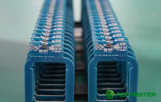
How Is a 100 Ohm Resistor Used in PCB Design?
A 100 Ohm resistor is commonly used in PCB design for current limiting, signal handling, component protection, and circuit reliability. It is designed for analog circuits, digital systems and power management boards that have a common resistance value.
Typical PCB Applications
So a 100 Ohm resistor will be used in different PCB designs depending on what electrical function is required. It can control the current, stabilize the signal and shield sensitive parts from electrical stress.
Analog Circuit
100 Ohm resistor is commonly utilized in Analog PCB circuits to modulate signal, control current and stabilize the circuit.
Standard applications are:
- Sensor signal conditioning
- Audio circuits
- Amplifier input and output networks
- Analog measurement systems
For example, in a sensor circuit, a 100Ω resistor may reduce the current through the detecting element and help make the signal more stable. It can be used with capacitors in audio circuits to reduce unwanted noise in the circuit and improve signal quality.
Engineers choose the 100 Ohm resistor with respect to the resistor tolerance and temperature coefficient. Analog circuits are often assumed to be reliable and predictable.
Electronic Digital Circuits
In digital PCB design , a 100 Ohm resistor is often used for signal control and protection .
Common uses include:
- Microcontroller circuits
- Communication interfaces
- High-speed digital signals
- Data transmission lines
For example, a 100Ω resistor could be inserted in parallel with the microcontroller output pin to avoid the signal ringing. It dampens the effects of sudden voltage changes, and helps to avoid signal distortion from reflections or electromagnetic interference.
It is common practice in high speed communication systems to use a 100 Ohm termination resistor to match the differential signal line impedance, to increase signal integrity and reduce transmission errors.
Power Management Boards
In power management circuits, 100 Ohm resistors are commonly used as current limiting, feedback control and safety features.
The examples are:
- Power supply control circuits
- Battery management systems
- Voltage monitoring circuits
- Charging circuits
For example, a 1000 resistor limits the current going into a control signal line, protecting a powermanagement IC from high current. Power circuits can produce more heat than low power signal circuits.Engineers must take care to calculate power dissipation.
PCB Layout Considerations
Good PCB layout is important since the location and routing of a 100 Ohm resistor can influence the performance, heat dissipation and reliability of the circuit.
Component Locations
So a 100 Ohm resistor on a PCB should be put where its electrical function dictates that it should be.
Important factors to consider when placing are:
- Keep signal-related resistors close to the connected components.
- Place protection resistors near input or output pins.
- Keep high-current resistor paths short.
If you are using a 100Ω resistor to protect a microcontroller pin then you want to keep the resistor near to the pin to reduce unwanted noise and improve signal performance.
In high speed circuits, the placement of resistors is highly crucial. Long traces can cause signal reflection and interference.
Trace Routing
The routing of a 100 Ohm resistor can have a big impact on performance in signal applications .
Best routing practices include:
- Keep signal traces short.
- Avoid unnecessary trace bends.
- Maintain proper spacing from noisy power lines.
- Use controlled impedance routing when required.
For example, a 100Ω termination resistor used in the communication circuit should be located at the end of the signal line. If not correctly located , the effectiveness of signal termination can be impaired .
Thermal Management
Many 100 Ohm resistors are low power, but in higher current applications, heat control is still a consideration.
Engineers should consider:
- Resistor power rating
- PCB copper area
- Airflow conditions
- Nearby heat-producing components
For example a 100Ω resistor near it's maximum rated power may have to be in a bigger package or have more copper area to prevent it overheating.
Good thermal design keeps the stability of resistance and prolongs the service life of PCB assembly.
Surface-Mount vs . Through-Hole on PCBs
The decision to use surface-mount or through-hole 100 Ohm resistors depends on the size of the PCB, manufacturing restrictions, power needs and reliability needs.
Manufacturing Variability
They are 100 Ohm surface mount ( SMD ) resistors . This implies that they are soldered to the surface of the PCB . There are other resistors that are via hole. They have leads that pass through holes in the pcb .
Key differences:
| Feature | SMD 100Ω Resistor | Through-Hole 100Ω Resistor |
|---|---|---|
| Mounting method | Mounted on PCB surface | Leads inserted through PCB holes |
| Size | Smaller | Larger |
| Automation | Excellent for automated assembly | More suitable for manual or selective assembly |
| PCB space | Requires less space | Requires more space |
SMD resistors are common in small circuits today but through hole resistors are still found in high power and mechanically challenging applications.
Assembly Methods
SMD 100 Ohm resistors are generally placed by automated pick and place machines and then reflow soldered in place.
Benefits include:
- Faster production
- Higher component density
- Lower manufacturing cost for large volumes
Generally, through hole resistors require:
- Manual insertion
- Wave soldering
- Selective soldering
They are often specified for products that require more robust mechanical fastening.
Reliability Comparison
Either type of resistor will deliver reliable service if the selection is proper.
Advantages of SMD Resistors:
- Smaller size
- Better for compact PCB designs
- Suitable for high-volume production
Advantages of Through Hole Resistors:
- Stronger mechanical connection
- Better for vibration environments
- Easier manual replacement during repair
For example, an automotive control PCB that is sensitive to vibration may use through-hole components in some parts of the PCB, yet a smartphone PCB will almost always use SMD resistors due to very tight space limits.
Design Best Practices
And a good design technique ensures that a 100 Ohm resistor will perform safely and reliably for the life of the PCB.
Selecting the Right footprint
The PCB footprint should be identical in physical size and electrical specifications to the resistor you select.
Here are some of the highlights:
- Package size
- Pad dimensions
- Soldering method
- Component availability
For example, choosing the improper footprint for an SMD 0603 or 0805 100Ω resistor may cause soldering challenges, faulty contacts or manufacturing defects.
Power dissipation accounting
You will build your PCB using a 100 Ohm resistor. Just compute the electricity usage projected.
Engineers shall examine:
- Operating voltage
- Current flow
- Maximum power rating
- Safety margin
For instance, a small signal circuit may only need a 100Ω resistor rated at 0.125W, whereas a power control circuit may require a resistor rated at 1W or more.
Select the power rating appropriately to avoid overheating and to promote long term reliability.
Improving long-term reliability
A reliable PCB design is not just about choosing the proper resistance value.
Engineers should also consider:
- Resistor tolerance
- Temperature coefficient
- Environmental conditions
- Component quality
- Manufacturing standards
For example, a 100 Ohm resistor with low temperature drift and high reliability certification may be required for industrial or automotive PCB applications to guarantee continuous performance in the face of temperature changes and vibration.
The designer chooses the proper resistor type, footprint and operating margin such that a 100 Ohm resistor will perform consistently during the product lifecycle.

How Does a 100 Ohm Resistor Compare with Other Common Resistor Values?
100 Ohm resistor has lesser resistance than 220Ω, 330Ω or 1kΩ. This enables more current through. The best choice depends on the circuit requirements such current regulation, signal performance, power consumption and application purpose.
100 Ohm vs . 220 Ohm
If you have a 100 Ohm resistor, it will carry twice the current of a 220 Ohm resistor, given the same voltage. It has less opposition .
Ohm's Law tells us:
Current = Voltage ÷ Resistance
For example, using a 5 V supply:
100Ω resistor
- Current = 5V ÷ 100Ω = 50mA
220Ω resistor:
- Current = 5V ÷ 220Ω ≈ 23mA
This difference makes a 100Ω resistor better for situations where you want more control of the current, but a 220Ω resistor better where you desire less current usage.
Typical uses are:
100 ohm resistor
- Signal termination
- Stronger current limiting
- Communication interfaces
- Driver circuits
Resistor 220 Ohm
- LED current limiting
- Low-power indicator circuits
- General-purpose protection
For example a red LED with a 100Ω or 220Ω resistor can be utilized. More up-to-date and hot. If you want a brighter LED you can use a 100 ohm resistor .
100 Ohm vs . 330 Ohm
The 100 Ohm resistor has a smaller voltage drop and provides a larger current than the 330 Ohm resistor. This is a very crucial distinction in led circuits.
LED Circuit 5V :
With 100Ω resistor:
- Higher current flow
- Brighter LED output
- More power consumption
With a 330 Ω resistor:
- Lower current flow
- Reduced LED brightness
- Lower power consumption
For example, supposing the LED has a forward voltage of 2V:
With a 100Ω resistor:
Current = (5V - 2V) ÷ 100Ω = 30mA
With 330 ohm resistor:
Current = (5V - 2V) ÷ 330Ω ≈ 9mA
If you need to drive the circuit with some more current , then a 100ohm resistor would be fine . For energy saving, a resistor of 330Ω is usually employed.
The voltage across the resistor also changes. The lower the value of the resistance, the lower the voltage dropped across the resistor for a given current. The higher the resistance value, the more voltage it takes.
100 Ohm vs . 1k Ohm
1k Ohm resistor 100 Ohm resistor The resistance is changed by a factor of 10. Various circuit functionalities are employed.
A 1k resistor will restrict current significantly more than a 100 Ohm resistor.
For example if the supply voltage is 5V:
100 Ohm
- Current = 50mA
1kΩ
- Current = 5mA
So the 1kΩ resistor is better suited for low power signal circuits where lower current consumption is required.
Applications of Signals
100Ω Resistor is used in :
- High-speed signal termination
- Signal damping
- Interface protection
Common uses of a 1kΩ resistor:
- Pull-up circuits
- Pull-down circuits
- Sensor interfaces
- Microcontroller inputs
Power Consumption
A 1kΩ resistor allows less current to travel through it therefore it generally produces less heat and uses less power.
For example, for battery powered devices, you might want a 1k resistor, as this might prevent excessive waste of current.
But high resistance value is not always good. In high speed digital circuits, too big a resistor can block signal transitions and result in poor signal control. Engineers select between 100Ω or 1kΩ depending on the electrical performance required.
Comparison Table
| Feature | 100 Ohm Resistor | 220 Ohm Resistor | 330 Ohm Resistor | 1k Ohm Resistor |
|---|---|---|---|---|
| Resistance level | Low | Medium-low | Medium | High |
| Current flow | Higher | Lower than 100Ω | Lower than 220Ω | Much lower |
| Power consumption | Higher | Moderate | Lower | Lowest |
| Common use | Signal control, termination, current limiting | LED circuits, protection | LED circuits, low-power applications | Pull-up, pull-down, sensors |
| LED brightness | Higher | Medium | Lower | Very low |
| Signal speed | Faster response | Moderate | Moderate | May reduce speed in some circuits |
| Heat generation | Higher at same voltage | Lower | Lower | Lowest |
This comparison illustrates that the 100 Ohm resistor is a wise choice if the circuit requires a stronger control of the current without too much resistance.
When Should You Choose a 100 Ohm Resistor?
You can use a 100 Ohm resistor if you need modest current management, signal stability or impedance matching in your circuit. This is a typical choice in engineering as it provides a reasonable balance between performance and power usage.
Selection Criteria
Some thoughts about choosing a 100 Ohm resistor:
1. Now required
- Use Ohm’s Law to calculate expected current.
- Confirm that the current level matches the circuit requirements.
2. Power Rating
- Calculate resistor power consumption.
- Select a wattage rating with enough safety margin.
3. Tolerance requirements
- Use ±5% for general circuits.
- Choose ±1% or better for precision applications.
4. Package Typ e
- Select SMD packages for compact PCB designs.
- Use through-hole resistors for higher mechanical strength or easier repair.
Performance Problems
A decent choice for this circuit is a 100Ω resistor.
- Faster signal response compared with higher resistance values
- Controlled current flow
- Stable signal transmission
- Reduced signal reflection in communication lines
Engineers must not use a 100Ω resistor if the circuit is supposed to consume very low power or let very weak current flow. In this scenario a larger value resistor like 1k or 10k may be more acceptable .
Engineering Typical Cases
These scenarios are often handled with a 100 Ohm resistor:
1. Current limitation for LEDs.
- Protects LEDs from excessive current
- Controls brightness
- Improves component lifespan
2. Rapid communication circuits
- Provides signal termination
- Reduces signal reflection
- Improves data reliability
3. Protection for microcontrollers
- Limits current between pins and external devices
- Helps protect input/output circuits
4. Signal conditioning for PCBs
- Reduces noise
- Controls signal transitions
- Improves circuit stability
5. Build and test prototype circuits.
- Provides a common reference resistance value
- Easy to source and replace
In practical PCB design, 100 Ohm resistor is used as a balance between the requirement for current, signal performance, power consumption and reliability. But knowing how it fits into other resistor levels can help engineers select the right one for the job.
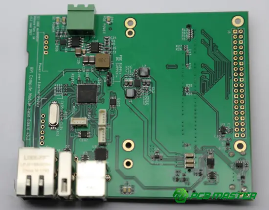
How Do You Select the Right 100 Ohm Resistor for Your Project?
Selection of the right 100 Ohm resistor is based on taking into consideration electrical need, tolerance, package type, environmental conditions and PCB manufacturing requirements. It guarantees the consistency in performance, avoids overheating and boosts the product durability with correct selection.
Determine Electrical Requirements
If you need to get a 100 Ohm resistor the first thing you need to do is understand the electrical parameters of your circuit ( voltage, current and power requirements).
Voltage
The voltage will control how much electrical stress the 100 Ohm resistor will experience. Thus the voltage across the resistor is larger . The larger the voltage across the resistor , the larger the power .
Work out what voltage you expect before you select a resistor.
Voltage (V) = Current (I) × Resistance (R)
For example, a 100Ω resistor with 50mA current:
V = 0.05A × 100Ω = 5V
So the resistor will see 5V across it.
The engineers must make sure that the rated voltage of the resistor is higher than the actual voltage in the circuit so that the component does not fail.
Current
The current determines how much electricity flows through the 100 Ohm resistor . The greater current , the more heat , the higher the power rating of the resistor you need .
For example:
- Low-current signal circuit → standard 100Ω resistor
- High-current power circuit → higher wattage 100Ω resistor
This is known as Ohm's law:
I = V ÷ R
A 5 volt source across a 100Ω resistor yields:
I = 5V ÷ 100Ω = 50mA
Engineers know the current and hence can choose the correct resistor rating.
Power
The power rating is one of the most important features when selecting a 100 Ohm resistor.
The power formula is:
P = V² ÷ R
For example:
lVoltage: 10V
lResistance: 100Ω
P = 10² ÷ 100 = 1W
The resistor should be rated for more power than it dissipates. Designers often employ a resistor with some safety margin to improve reliability.
Choose the Correct Tolerance
It depends on how accurate the circuit needs to be to maintain the 100 Ohm resistance figure.
Tolerance is the permissible variation between the actual resistance and the stated value.
Application Accuracy
The 100 Ohm resistors are used in precision circuits where any small change in resistance would affect the accuracy of the measurement.
Options include:
- ±1% tolerance
- ±0.5% tolerance
- ±0.1% tolerance
Applications include:
- Measurement equipment
- Calibration systems
- Sensor circuits
- Control systems
For instance, a measurement circuit for temperature would use a precise 100O resistor, because a tiny variation in the resistance would give an incorrect value.
General Purpose Applications
Usually a standard tolerance resistor is sufficient for ordinary electronic circuits.
Some common options are:
- ±5% Tolerance
- ±1% Tolerance
commonly used resistor of +/-5% 100 Ohm in:
- LED circuits
- Basic control circuits
- Consumer electronics
- General PCB designs
Choosing a resistor with a higher accuracy than you really need will cost you more money and will not improve the performance of your circuit.
Select the Appropriate Package
The choice of the 100 Ohm resistor package will be dictated by the PCB area, assembly method and power requirements.
Through Hole
The leads of the 100Ω resistors through-hole go through the holes of the PCB.
Advantages:
- Strong mechanical connection
- Easy manual installation
- Suitable for higher-power designs
Common applications include:
- Industrial equipment
- Power electronics
- Prototypes
- Repairable products
For example, a motor control board that is sensitive to vibration might use through-hole resistors because they provide better physical support.
SMD
100 Ohm SMD resistors Surface mount devices (SMD) are soldered to the surface of the PCB.
The good points:
- Small size
- Supports automated assembly
- Allows higher component density
Typical sizes of SMDs are:
- 0201
- 0402
- 0603
- 0805
- 1206
SMD Resistors used in :
- Smartphones
- Wearable devices
- Embedded systems
- High-volume PCB production
For compact PCB designs SMD 100Ω resistors are often the way to go.
high power choices
Some applications require a high power 100 Ohm resistor that can dissipate a lot of heat.
High power resistors are most often:
- Larger physical size
lBetter heat dissipation
Higher wattage ratings
They are useful for:
- Power supplies
- Load testing systems
- Motor control circuits
For example a 100Ω resistor in a power circuit may have to be rated at 5W or 10W rather than a standard 0.25W resistor.
Consider Environmental Conditions
The performance and life of a 100 Ohm resistor can be affected by environmental conditions. The type of resistor depends on the working conditions of PCB.
Operating temperature
Temperature influences the resistance value and the reliability of components.
The main issues are:
- Maximum operating temperature
- Temperature coefficient (TCR)
- Heat generated by nearby components
For example, a resistor with better temperature stability is required for an automotive PCB near an engine than a consumer device used indoors.
Humidity
High humidity can affect PCB materials, solder joints and component reliability.
In humid circumstances engineers may utilize:
- Resistors with protective coatings
- Components with moisture resistance ratings
- Proper PCB protection methods
And especially for outdoor electronics and industrial equipment .
Stress in Mechanics
Mechanical elements like as vibration, tension and bending might affect the reliability of the resistor.
Examples of applications where a higher mechanical performance is required are:
- Automotive electronics
- Industrial machines
- Aerospace equipment
If mechanical endurance is a major concern, you can use through-hole resistors or specially developed SMD parts.
Follow PCB Manufacturing Requirements
The PCB manufacturing method needs to be matched with a suitable 100 Ohm resistor for efficient assembly and reliable production.
Assembly Compatibility
The resistor package has to be compatible with the PCB fabrication process.
Consider:
- SMT compatibility
- Soldering process
- Pick-and-place machine requirements
- PCB footprint accuracy
SMD resistors are often chosen for high volume manufacturing because they are compatible with automatic assembly.
Parts Availability
The availability of components affects the stability of production.
Engineers should consider:
- Supplier availability
- Lead times
- Alternative part options
- Long-term supply support
For example, using a common 0603 100Ω resistor is less risky for production than using a unique component.
Standards of Reliability
In several industries, resistors are required to meet particular reliability standards.
As an example:
- Automotive electronics
- Medical devices
- Industrial control systems
The components engineers might choose are based on:
- Quality certifications
- Operating temperature range
- Long-term stability
- Manufacturer reliability data
The right 100 Ohm resistor for PCB applications is not merely the value of resistance. The selection is extensive and considers electrical performance, physical design, climatic conditions and manufacturing requirements to provide reliable operation throughout the product life cycle.
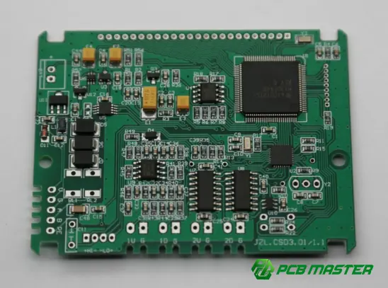
What Common Mistakes Should You Avoid When Using a 100 Ohm Resistor?
The most typical problems when utilizing a 100 Ohm resistor are choosing the wrong power rating, misinterpreting resistor markings, not considering tolerance, picking an incorrect package, not considering heat generation and putting the wrong resistance on the pcb during assembly. Avoiding these problems can help to guarantee that your circuit is safe and reliable over the long run.
Choosing an Incorrect Power Rating
The suitable power rating should be chosen as the 100 Ohm resistor will turn the electrical energy into heat while it operates.
A common mistake is to select a resistor based on resistance value exclusively, ignoring power usage. A 100Ω resistor in a low current signal circuit could only need a 0.125W or 0.25W rating whereas the same resistor in a power circuit might need a significantly larger wattage rating.
The power dissipated by a resistor can be estimated via:
P = V² ÷ R
For instance:
- Voltage: 10V
- Resistance: 100Ω
P = 10² ÷ 100 = 1W
In this case a 0.25W ordinary resistor would get too hot.
Here’s what happens when you use a too-small resistor:
- Excessive temperature rise
- Resistance value drift
- Component failure
- PCB damage
Engineers should always calculate the predicted power and select a 100 Ohm resistor with enough safety margin.
Misreading the Color Code
A frequent reason for choosing the wrong 100 Ohm resistor value is a misinterpretation of the resistor color bands.
A typical 4 band 100 Ohm resistor color code is:
Brown – Black – Brown – Gold
Meaning:
- Brown = 1
- Black = 0
- Brown multiplier = ×10
- Gold = ±5% tolerance
This yields:
10 × 10 = 100Ω
The usual problem is reading the resistor from the wrong direction. The tolerance band, usually gold or silver, should be used as a reference point as it is usually isolated from the value bands.
For instance, if a 100Ω resistor is mistakenly swapped for a 1kΩ resistor, it may cause problems in the circuit as the current will be ten times different.
Always verify the value before installation with:
- Color code identification
- Manufacturer markings
- Digital multimeter measurement
Ignoring Tolerance Requirements
Ignoring resistor tolerance might result in circuit performance not meeting expectations, especially in precision applications.
A 100 Ohm resistor won't always read 100Ω. The real value relies on its tolerance rating.
Examples are:
100Ω ±5%
- Actual range: 95Ω to 105Ω
100Ω ±1%
- Actual range: 99Ω to 101Ω
In simple applications like LED indicators, a ±5% resistor is generally good enough.
But circuits with:
- Sensor measurement
- Calibration
- Analog signal processing
- Precision control systems
may need a resistor with closer tolerance.
If you need a precise resistor but use a regular one, it may result in:
- Incorrect voltage levels
- Measurement errors
- Reduced system accuracy
Engineers must set tolerances based on the performance needs of the circuit and not only the lowest price.
Selecting the Wrong Package Type
The improper choice of the resistor package may lead to PCB assembly troubles, space issues or reliability issues.
There are several different package types for a 100 Ohm resistor such as:
- Through-hole resistors
- SMD resistors
Selecting the wrong package can cause problems such as:
- Incorrect PCB footprint
- Soldering defects
- Poor mechanical stability
- Insufficient power handling
For example:
- A 0402 SMD 100Ω resistor is suitable for compact consumer electronics.
- A large through-hole 100Ω resistor may be better for high-power or vibration environments.
When choosing a bundle, consider:
lPCB size
- Assembly method
- Power requirements
- Operating environment
Matching the resistor package to the PCB design eliminates manufacturing concerns.
Overlooking Heat Generation
The heat generation is a significant factor since the durability of a 100 Ohm resistor might be affected at too high a temperature.
Even if the resistor has the right resistance, it can still fail if it is stressed near its power rating over a lengthy period of time.
Heat concerns may be caused by:
- High current flow
- Limited airflow
- Nearby heat-producing components
- Incorrect wattage selection
For example, a 100Ω resistor located near a power transistor may receive increased heating from the surrounding environment.
To increase reliability:
- Select a resistor with extra power margin
- Consider the PCB thermal design
- Check the operating temperature range
- Use a suitable resistor package
Generally, a resistor below its maximum rating will give better long-term stability.
Installing the Wrong Resistance Value During PCB Assembly
If a resistor is functioning properly, but has the improper resistance value when placed on a PCB during assembly, the circuit may not function appropriately.
PCB manufacture is not error free either . Many resistors look same, especially the little SMD ones .
Common errors in assembly are:
- Installing 1kΩ instead of 100Ω
- Using 10Ω instead of 100Ω
- Placing the wrong component on the correct footprint
These mistakes can lead to:
- Incorrect current levels
- Signal errors
- Component overheating
- Circuit failure
For example, changing a needed 100Ω signal termination resistor to a 1kΩ resistor can cause signal reflection and communication difficulties in high-speed circuits.
Manufacturers employ to avoid assembly errors:
- Component verification systems
- Automated optical inspection (AOI)
- Bill of materials (BOM) checks
- Electrical testing
The right component is identified and quality checked to ensure the right 100 Ohm resistor is placed and functions as it should in the final PCB assembly.
Conclusion
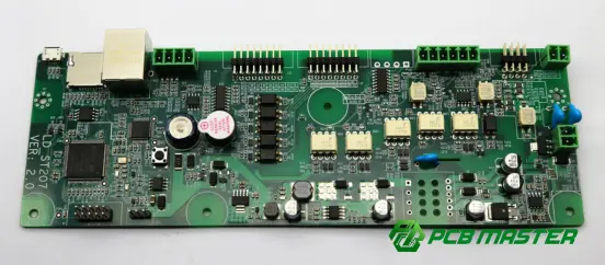
To get the perfect 100 Ohm resistor, just selecting a part with the exact resistance value is not enough. Many factors affect the reliable operation of the circuit such as tolerance, power rating, packaging type, temperature stability, application requirements etc. In properly executed applications that need current limiting, signal conditioning, PCB protection, or testing, a 100Ω resistor can provide benefits such as improved circuit stability and product reliability.
With electronic designs becoming more complicated and dense, it is increasingly critical to pick parts that meet electrical and manufacturing criteria. An professional PCB partner can help make each choice of components work for the performance of the final product as a whole.
PCBMASTER is a professional maker of PCB, PCBA assembly and electrical solutions . Professional engineering support and quality-conscious production procedures help our customers to produce reliable and efficient designs. PCBMASTER is dedicated to offering PCB solutions for different industrial demands from prototype to mass production.
Frequently Asked Questions About 100 Ohm Resistors
Can a 100 Ohm resistor be used as an LED current-limiting resistor?
If you have enough voltage, LED forward voltage and current you require, you can use a 100 Ohm resistor as an LED current limiting resistor.
The value of the resistor is:
R = (Supply Voltage - LED Forward Voltage) ÷ LED Current
Let’s say we have a 5V power supply and a red LED that has a forward voltage of 2V and we want to run it at 30mA:
R = (5V - 2V) ÷ 0.03A = 100Ω
The 100 Ohm resistor is a smart choice here, limiting the LED current to a safe value.
But a 100Ω resistor might not be the correct resistance for every LED circuit. If the supply voltage is higher or the LED needs less current then a larger value of resistance may be required. Also check the power rating of the resistor and ensure it can handle the heat that it will release in use.
What color bands indicate a 100 Ohm resistor?
The 100 Ohm resistor can come in several combinations of color bands depending on whether it is designated with a 4-band or 5-band marking system.
For 4 band 100 Ohm resistor the color code is:
Brown – Black – Brown – Gold
That is to say:
- Brown = 1 (first digit)
- Black = 0 (second digit)
- Brown = ×10 multiplier
- Gold = ±5% tolerance
Calculation:
10 × 10 = 100Ω
5 band 100 Ohm resistor color code:
Brown – Black – Black – Black – Brown
The sense is:
- Brown = 1
- Black = 0
- Black = 0
- Black = ×1 multiplier
- Brown = ±1% tolerance
The first three bands yield the number 100 and the multiplier leaves the value at 100Ω.
How can I test whether a 100 Ohm resistor is working correctly?
Set your digital multimeter to resistance (Ω) mode to test a 100 Ohm resistor.
Do the following:
1. Turn off the circuit power.
2. Remove the resistor from the circuit if possible.
3. Set the multimeter to the resistance measurement mode.
4. Place the probes on both resistor terminals.
5. Compare the measured value with the expected resistance.
The resistor tolerance specifies the range of permissible measurements:
- 100Ω ±5% resistor: 95Ω to 105Ω
- 100Ω ±1% resistor: 99Ω to 101Ω
If the measured value is far from this range, it could be due to the resistor being broken, misdiagnosed or affected by other components connected in the circuit.
To test a resistor properly you are best measuring its value out of the circuit . Other parts can interfere with the measurement.
Is a 100 Ohm resistor suitable for high-power applications?
100 Ohm resistor with enough power rating for the electrical load for high power applications.
The value of the resistance alone can not determine the use of a resistor for high power. Wattage is the important factor.
Power can be calculated as:
P = V² ÷ R
For example:
- Resistance: 100Ω
- Voltage: 20V
P = 20² ÷ 100 = 4W
A regular 0.25W 100Ω resistor will not do the job here. You need a resistor rated at more than 4W.
For high power applications it may be required to:
- Larger resistor packages
- Better heat dissipation
- Wirewound or power resistor types
Hence a 100Ω resistor can be utilized in a high power circuit only provided the selected component has the correct power rating and thermal design.
Can I replace a 100 Ohm resistor with a 120 Ohm resistor?
Sometimes you can replace a 120 Ohm resistor with a 100 Ohm one, but it depends on the circuit application.
The 120Ω resistor has 20% greater resistance, hence it will lower the current flow than the 100Ω resistor.
For example the LED circuit:
- 100Ω resistor → Higher current and brighter LED
- 120Ω resistor → Lower current and slightly reduced brightness
For many simple circuits this little modification may be quite adequate. Replacement such as: could introduce issues in circuits where the resistance levels need to be exact:
- Signal termination circuits
- Timing circuits
- Precision measurement systems
- Impedance-controlled designs
Before you replace a 100Ω resistor, think:
- Required current level
- Voltage drop changes
- Power consumption
- Circuit tolerance requirements
A 120Ω resistor can be used as a replacement for general purpose applications. However, for high-speed PCB designs, or for precision, the desired 100Ω is optimal.
About the Author

Carol Luo
PCB Design EngineerI'm Carol, a PCB Engineer at PCBMASTER with experience in PCB design and manufacturing engineering since 2018. I focus on translating engineering requirements into reliable PCB solutions, with expertise in stack-up design, material selection, and design-for-manufacturing (DFM). I share practical engineering insights from real-world PCB design and production experience.
Visit Carol Luo's Profile

