








Potentiometer vs. Variable Resistor: Types, Working Principle, Applications, and Selection Guide
A potentiometer is a three-terminal variable resistor primarily used to divide voltage, while a variable resistor (often called a rheostat ) typically uses two terminals to regulate current by changing resistance. Both components are widely used in PCB design, consumer electronics, industrial equipment, automotive systems, and embedded control circuits. Choosing the right type requires evaluating resistance value, taper, power rating, mounting style, environmental conditions, and PCB assembly compatibility. This guide explains how potentiometers and variable resistors work, compares their differences, explores common applications, and provides practical selection advice for engineers and product developers.
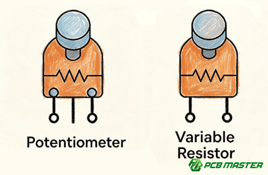
What Is a Potentiometer?
A potentiometer (pot) is a three-terminal passive component with an adjustable resistive element. By rotating a shaft or moving a slider, the wiper changes position along the resistive track, producing a variable output voltage.
Unlike fixed resistors, potentiometers allow continuous adjustment, making them ideal for calibration, user controls, and analog signal tuning.
Typical characteristics include:
- Three electrical terminals
- Adjustable resistance ratio
- Functions as a voltage divider
- Manual or motorized adjustment
- Available in through-hole and SMD packages
Potentiometers are commonly found in:
- Audio equipment
- Industrial controllers
- Medical devices
- Test instruments
- Consumer electronics
- Automotive electronics
What Is a Variable Resistor?
A variable resistor is a resistor whose resistance can be adjusted manually or electronically.
The term is broad and includes several adjustable resistor types:
- Potentiometers
- Rheostats
- Trimmer potentiometers
- Digital potentiometers
In many engineering discussions:
- Potentiometer refers to the three-terminal voltage divider.
- Rheostat refers to the two-terminal current-controlling variable resistor.
How Does a Potentiometer Work?
A potentiometer contains:
- Resistive element
- Wiper
- Three terminals
Terminal A and Terminal B connect to each end of the resistive track.
The center terminal connects to the movable wiper.
When the shaft rotates:
- Resistance between the wiper and Terminal A changes.
- Resistance between the wiper and Terminal B changes.
- Total resistance between A and B remains constant.
This creates a continuously adjustable output voltage.
Potentiometer vs. Variable Resistor
| Feature | Potentiometer | Variable Resistor (Rheostat) |
|---|---|---|
| Number of terminals | Three | Two |
| Primary function | Voltage division | Current control |
| Typical circuit | Signal adjustment | Power regulation |
| Common applications | Volume control, sensors | Motor speed, heaters, lighting |
| Power handling | Usually low to medium | Medium to high |
| Output | Adjustable voltage | Adjustable resistance |
Key takeaway: Every potentiometer is an adjustable resistor, but not every adjustable resistor is used as a potentiometer.
Main Types of Potentiometers
Rotary Potentiometer
The most common type.
Applications include:
- Audio volume
- Industrial equipment
- Home appliances
- Laboratory instruments
Advantages:
- Low cost
- Long life
- Easy operation
Slide Potentiometer
The wiper moves linearly instead of rotating.
Common in:
- Audio mixers
- Lighting consoles
- Control panels
Advantages:
- Intuitive adjustment
- High positioning accuracy
Trimmer Potentiometer
A small adjustable potentiometer intended for PCB calibration.
Typical uses include:
- Offset adjustment
- Sensor calibration
- Reference voltage tuning
- Factory calibration
Most are adjusted using a screwdriver and are not intended for frequent user operation.
Digital Potentiometer
Instead of a mechanical wiper, digital potentiometers use integrated electronic switches.
Advantages:
- MCU control
- High repeatability
- No mechanical wear
- Remote adjustment
Applications include:
- IoT devices
- Industrial automation
- Smart instruments
- Medical electronics
Potentiometer Taper Types
The taper describes how resistance changes as the shaft rotates.
| Taper | Characteristics | Typical Applications |
|---|---|---|
| Linear | Resistance changes uniformly | Power supplies, industrial control |
| Logarithmic (Audio) | Matches human hearing | Audio volume control |
| Reverse Log | Opposite of logarithmic | Specialized audio circuits |
Selecting the correct taper is essential for achieving the desired control response.
Common Resistance Values
Typical potentiometer resistance values include:
| Resistance |
|---|
| 100 Ω |
| 500 Ω |
| 1 kΩ |
| 2 kΩ |
| 5 kΩ |
| 10 kΩ |
| 20 kΩ |
| 50 kΩ |
| 100 kΩ |
| 500 kΩ |
| 1 MΩ |
The appropriate value depends on circuit impedance, current requirements, and signal conditioning needs.
Applications in PCB Design
Potentiometers remain widely used across PCB designs for adjustment and calibration.
Common applications include:
Audio Electronics
- Volume control
- Tone adjustment
- Gain control
Power Supplies
- Output voltage adjustment
- Current limiting
- Calibration
Industrial Automation
- Position adjustment
- Speed control
- Analog input settings
Automotive Electronics
- Dashboard controls
- HVAC systems
- Sensor calibration
Medical Equipment
- Precision calibration
- Gain adjustment
- User interface controls
Laboratory Instruments
- Signal calibration
- Measurement adjustment
- Reference voltage setting
How to Choose the Right Potentiometer
Selecting the right potentiometer involves more than resistance value alone.
1. Resistance Value
Choose based on circuit impedance.
Common values include:
- 1 kΩ
- 5 kΩ
- 10 kΩ
- 50 kΩ
- 100 kΩ
2. Taper
- Linear
- Audio (Log)
- Reverse Log
3. Power Rating
Ensure the component can safely dissipate power without overheating.
Typical ratings:
- 0.05 W
- 0.1 W
- 0.25 W
- 0.5 W
- 1 W
- Higher for rheostats
4. Mounting Style
Available options include:
- Through-hole
- Surface mount (SMD)
- Vertical
- Horizontal
- Panel mount
The mounting style should match your PCB layout and enclosure design.
5. Mechanical Life
For products with frequent adjustment, choose components rated for high cycle life.
Typical ratings range from:
- 10,000 cycles
- 50,000 cycles
- 100,000+ cycles
6. Environmental Requirements
Consider:
- Operating temperature
- Humidity
- Dust protection
- Vibration
- Automotive qualification
PCB Design Considerations
Proper PCB design improves reliability and assembly quality.
Key recommendations include:
- Place adjustment points in accessible locations.
- Maintain adequate mechanical clearance for knobs or sliders.
- Avoid routing sensitive analog traces near noisy switching circuits.
- Provide sufficient copper area for high-power variable resistors.
- Secure large panel-mounted components to reduce solder joint stress.
- Follow manufacturer-recommended footprints and keep-out areas.
For trimmer potentiometers, leave enough space for calibration tools during production and maintenance.
Common Design Mistakes
| Mistake | Potential Impact | Recommended Practice |
|---|---|---|
| Choosing the wrong taper | Poor user experience | Match taper to application |
| Ignoring power rating | Overheating or failure | Calculate worst-case power dissipation |
| Inaccessible placement | Difficult adjustment | Ensure tool or user access |
| Poor mechanical support | Cracked solder joints | Add mounting support where needed |
| Incorrect footprint | Assembly issues | Verify datasheet dimensions before layout |
PCB Assembly Considerations
The reliability of adjustable components depends on both design and manufacturing quality.
During PCB assembly, manufacturers should verify:
- Correct footprint dimensions
- Proper solder joint quality
- Component orientation
- Mechanical stability
- Functional adjustment after assembly
For products requiring high reliability, design-for-manufacturing (DFM) reviews can identify potential issues before production. PCBMASTER provides free engineering file checks to evaluate manufacturability, optimize layouts, and help reduce production risks before fabrication begins. Its capabilities cover everything from quick-turn prototypes to high-volume PCB and PCBA production for industries including industrial control, automotive electronics, communications, and consumer devices.
Future Trends
The use of potentiometers continues to evolve alongside modern electronics.
Emerging trends include:
- More digital potentiometers in smart devices
- Smaller SMD packages
- Higher precision resistance tolerance
- Automotive-grade reliability
- Integration into IoT and industrial automation systems
- Increased use in low-power embedded electronics
While digital control is expanding, mechanical potentiometers remain indispensable where intuitive manual adjustment and cost-effective analog control are required.
Conclusion
Potentiometers and variable resistors are essential components in electronic circuit design, offering simple and reliable methods for adjusting voltage, current, and signal levels. Understanding the differences between potentiometers, rheostats, trimmers, and digital potentiometers helps engineers select the most appropriate solution for each application.
Equally important is ensuring that these components are integrated into a well-designed PCB and assembled with consistent manufacturing quality. Experienced PCB and PCBA manufacturers such as PCBMASTER support this process through DFM review, precision fabrication, comprehensive testing, and flexible production capabilities, helping transform reliable circuit designs into dependable finished products.
Frequently Asked Questions
1. Is a potentiometer the same as a variable resistor?
No. A potentiometer is a type of variable resistor designed primarily as a voltage divider. A rheostat is a two-terminal variable resistor used mainly for current control.
2. What is the most common potentiometer value?
10 kΩ is one of the most widely used values because it suits many analog and control circuits.
3. Can a potentiometer be used as a rheostat?
Yes. By using only the wiper and one end terminal, a three-terminal potentiometer can function as a two-terminal variable resistor.
4. What is the difference between linear and logarithmic potentiometers?
Linear potentiometers change resistance uniformly, while logarithmic potentiometers provide a response that better matches human hearing, making them ideal for audio controls.
5. Are SMD potentiometers available?
Yes. Surface-mount potentiometers, especially trimmer types, are commonly used in compact electronic products and automated PCB assembly.
6. How do I choose the correct power rating?
Calculate the maximum expected power dissipation in the application and select a component with an appropriate safety margin.
Tags: #Potentiometer #VariableResistor #Rheostat #TrimmerPotentiometer #DigitalPotentiometer #PCBDesign #PCBA #SMT #Electronics #PCBMASTER #ElectronicComponents #CircuitDesign
About the Author

Carol Luo
PCB Design EngineerI'm Carol, a PCB Engineer at PCBMASTER with experience in PCB design and manufacturing engineering since 2018. I focus on translating engineering requirements into reliable PCB solutions, with expertise in stack-up design, material selection, and design-for-manufacturing (DFM). I share practical engineering insights from real-world PCB design and production experience.
Visit Carol Luo's Profile

