








Capacitors in Series: Formula, Equivalent Capacitance, Voltage Distribution, and PCB Applications
Capacitors connected in series behave differently from capacitors connected in parallel. The total or equivalent capacitance of series capacitors is determined by the reciprocal sum of their individual capacitances, meaning the equivalent capacitance is always lower than the smallest individual capacitor. Series capacitors are used in DC blocking, voltage distribution, energy storage, signal coupling, and specialized PCB circuits. Correct calculation of capacitance, voltage rating, leakage current, ESR, and capacitor tolerances is essential for reliable circuit design.
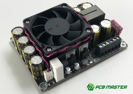
What Are Capacitors in Series?
Capacitors in series are connected end-to-end so that the same charge passes through each capacitor. Unlike parallel capacitors, where capacitance increases as additional capacitors are added, series connection reduces the overall equivalent capacitance.
A simple series arrangement can be represented as:
C₁ — C₂ — C₃
When a voltage is applied across the entire capacitor chain, the capacitors share the applied voltage according to their electrical characteristics.
For ideal capacitors connected in series, the equivalent capacitance is calculated using:
1/Ceq=1/C1+1/C2+1/C3+…+1/Cn
For two capacitors:
Ceq=C1C2/(C1+C2)
This is one of the most important formulas to remember when designing circuits containing capacitors in series.
Why Does Series Connection Reduce Capacitance?
Capacitance represents the ability of a capacitor to store electric charge for a given voltage. When capacitors are connected in series, the same charge magnitude is established on each capacitor, while the total voltage is distributed across them.
For capacitors in series:
Q1=Q2=Q3=…=Q
The total voltage is:
Vtotal=V1+V2+V3+…
Because each capacitor contributes part of the total voltage, the resulting equivalent capacitance is smaller than any individual capacitor in the chain.
Practical rule: When capacitors are connected in series, the equivalent capacitance is always less than the smallest individual capacitance.
How to Calculate Capacitors in Series
The calculation method depends on how many capacitors are connected.
Two Capacitors in Series
Suppose a circuit contains:
- C₁ = 10 µF
- C₂ = 20 µF
The equivalent capacitance is:
Ceq=10×20/(10+20)μF=6.67μF
Therefore, two capacitors rated at 10 µF and 20 µF do not produce 30 µF when connected in series. Their equivalent capacitance is approximately 6.67 µF .
Three or More Capacitors in Series
For three capacitors:
1/Ceq=1/C1+1/C2+1/C3
For example:
| Capacitor | Value |
|---|---|
| C₁ | 10 µF |
| C₂ | 20 µF |
| C₃ | 30 µF |
The equivalent capacitance is:
1/Ceq=(1/10+1/20+1/30) µF
which gives an equivalent capacitance of approximately 5.45 µF .
The more capacitors added in series, the smaller the equivalent capacitance becomes.
Identical Capacitors in Series
When all capacitors have the same capacitance, calculation becomes much easier:
Ceq=C/n
where:
- C = capacitance of one capacitor
- n = number of identical capacitors
For example, four 100 nF capacitors connected in series produce:
Ceq=100/4 nF=25 nF
This relationship is particularly useful when a specific effective capacitance is required but the designer wants to use multiple identical components.
How Voltage Is Distributed Across Series Capacitors
Voltage distribution is another critical consideration when capacitors are connected in series.
For ideal capacitors, the charge on each capacitor is the same. Since:
V= Q / C
a capacitor with a smaller capacitance experiences a larger voltage for the same charge.
For two series capacitors:
V1=Vtotal[C2/(C1+C2)]
and
V2=Vtotal[C1/(C1+C2)]
This means voltage does not necessarily divide equally between capacitors with different capacitance values.
Example of Voltage Distribution
Consider:
- C₁ = 10 µF
- C₂ = 20 µF
- Total voltage = 30 V
The equivalent capacitance is approximately 6.67 µF.
The voltage across C₁ is:
V1 =30× 20 /( 10+20 ) V =20V
The voltage across C₂ is:
V2 =30× 10 /( 10+20 ) V =10V
Therefore:
| Parameter | C₁ | C₂ |
|---|---|---|
| Capacitance | 10 µF | 20 µF |
| Voltage | 20 V | 10 V |
| Charge | Same | Same |
The smaller capacitor receives the larger voltage .
Capacitors in Series vs. Capacitors in Parallel
Understanding the difference between these two configurations is fundamental to PCB and electronic circuit design.
| Feature | Capacitors in Series | Capacitors in Parallel |
|---|---|---|
| Equivalent capacitance | Decreases | Increases |
| Charge | Same through each capacitor in the ideal model | Charge divides |
| Voltage | Divided across capacitors | Same across each capacitor |
| Equivalent capacitance formula | Reciprocal sum | Direct sum |
| Effective capacitance | Lower than the smallest capacitor | Higher than the largest capacitor |
| Typical purpose | Voltage distribution, higher effective voltage rating, AC coupling | Decoupling, filtering, energy storage |
For capacitors in parallel:
Ceq=C1+C2+C3+…
For capacitors in series:
1/Ceq=1/C1+1/C2+1/C3+…
A common design mistake is to apply the parallel formula to a series configuration. This can result in significant errors in circuit behavior.
Why Use Capacitors in Series?
Connecting capacitors in series is not simply a way to obtain a smaller capacitance. It can provide several useful electrical characteristics.
Increasing the Effective Voltage Capability
Multiple capacitors can sometimes be arranged in series when the voltage across an individual capacitor would otherwise exceed its suitable operating range.
However, designers should not simply add the voltage ratings and assume the resulting series combination is automatically safe . Real capacitors have leakage-current differences, tolerances, temperature dependencies, and aging characteristics.
Voltage balancing may therefore be required, particularly in high-voltage applications.
Obtaining a Specific Capacitance
Series combinations can provide an effective capacitance that is difficult to obtain with a single standard-value component.
For example, if the required capacitance falls between commonly available component values, a series combination can provide an alternative.
DC Blocking and AC Coupling
Capacitors naturally block steady-state DC while allowing changing signals to pass. Series capacitors are therefore frequently encountered in:
- AC coupling circuits
- Audio circuits
- Signal conditioning
- RF circuits
- Communication electronics
- Analog interfaces
The resulting impedance depends on the equivalent capacitance and signal frequency.
For an ideal capacitor:
XC=1/2πfC
A lower equivalent capacitance produces a higher capacitive reactance at the same frequency.
What Happens to ESR and Leakage Current?
Ideal capacitor equations are useful for initial calculations, but real components are not ideal.
A practical capacitor has parameters such as:
- ESR — Equivalent Series Resistance
- Leakage current
- Equivalent series inductance
- Capacitance tolerance
- Temperature coefficient
- DC-bias dependence
- Aging characteristics
When capacitors are connected in series, their ESR values contribute to the overall series impedance.
The effective capacitance can also differ from the nominal value, particularly when using ceramic capacitors whose capacitance may change with DC bias and temperature.
Leakage Current Matters in Voltage Sharing
One of the most important practical issues is unequal leakage current .
If two capacitors are connected in series across a DC voltage, their leakage characteristics may not be identical. Consequently, the voltage distribution can deviate from the ideal calculation.
For high-voltage applications, designers may use balancing resistors across individual capacitors to establish a more predictable DC voltage distribution.
How Capacitor Tolerance Affects Series Combinations
Capacitor tolerance should also be considered during design.
Suppose two capacitors are specified with nominal values but have relatively wide tolerances. Their actual capacitances can differ from the nominal values, changing both:
- The equivalent capacitance
- The voltage distribution
This becomes especially important when the circuit has strict electrical requirements.
For precision applications, engineers should evaluate the worst-case capacitance range , rather than calculating the circuit using nominal values only.
Common Design Mistakes When Using Capacitors in Series
Mistake 1: Adding Capacitance Directly
A frequent error is:
Ceq=C1+C2
That equation applies to parallel capacitors , not series capacitors.
For series capacitors, use the reciprocal relationship.
Mistake 2: Assuming Voltage Divides Equally
Two different capacitors do not necessarily share voltage equally.
The smaller capacitance generally experiences a greater voltage in the ideal steady-state model.
Mistake 3: Simply Adding Voltage Ratings
If two capacitors are connected in series, it is unsafe to assume that their voltage ratings can always be added directly.
Real-world voltage sharing depends on leakage current, tolerance, temperature, aging, and operating conditions.
Mistake 4: Ignoring DC Bias
For multilayer ceramic capacitors, the actual capacitance can decrease significantly under DC bias depending on the dielectric and component characteristics.
Using the nominal capacitance printed in a component database without checking operating conditions can therefore produce an inaccurate design.
Mistake 5: Ignoring PCB Layout
Even when the capacitance calculation is correct, PCB layout can influence circuit performance.
Parasitic inductance, trace impedance, loop area, grounding, component placement, and return paths become particularly important in high-frequency circuits.
Capacitors in Series in PCB Design
Series capacitors appear in many PCB applications, but their design requirements vary considerably according to the circuit's function.
High-Speed and RF PCB Applications
In high-speed designs, series capacitors are often used as AC-coupling components between circuit blocks.
The capacitor value must be selected according to:
- Signal frequency
- Characteristic impedance
- Receiver input impedance
- Desired low-frequency cutoff
- Package size
- ESR and ESL
- Signal integrity requirements
A capacitor that is electrically appropriate at low frequency may not provide the same behavior at high frequency because parasitic inductance becomes increasingly important.
Power Electronics
Series capacitor arrangements can appear in voltage-management and energy-storage circuits.
For these applications, engineers must evaluate:
- Working voltage
- Transient voltage
- Ripple current
- Temperature
- Leakage current
- ESR
- Lifetime
- Failure mode
For automotive and other demanding electronics, component selection and PCB manufacturing quality must also be considered together.
Analog and Mixed-Signal PCBs
Series capacitors are commonly used for signal coupling and DC isolation.
The resulting high-pass behavior depends on both the equivalent capacitance and the impedance of the surrounding circuit. Selecting an unnecessarily small equivalent capacitance can introduce excessive low-frequency attenuation.
Practical Design Checklist for Series Capacitors
Before releasing a PCB design for manufacturing, engineers should verify the following:
| Design Parameter | What to Check |
|---|---|
| Equivalent capacitance | Calculate using the series formula |
| Voltage distribution | Check voltage across each capacitor |
| Voltage rating | Evaluate worst-case operating and transient voltage |
| Capacitance tolerance | Calculate minimum and maximum values |
| Leakage current | Evaluate voltage-sharing behavior |
| ESR | Check impact on power and signal performance |
| Temperature | Verify capacitance and electrical stability |
| DC bias | Particularly important for MLCCs |
| Frequency | Evaluate impedance over the operating range |
| PCB layout | Minimize unwanted parasitic effects |
| Reliability | Consider lifetime, derating, and application environment |
How PCB Manufacturing Quality Influences Capacitor Circuits
Component selection is only one part of reliable electronic design. PCB fabrication and assembly quality can also affect the performance of circuits containing series capacitors.
Pad dimensions, solderability, component placement accuracy, solder joints, board cleanliness, and inspection quality all contribute to assembly reliability.
For complex PCB assemblies, engineering review before manufacturing can identify issues such as inappropriate footprints, insufficient spacing, or component placement conflicts before they reach production.
This is where design-for-manufacturing (DFM) becomes particularly valuable. A PCB manufacturer should evaluate not only whether a circuit can theoretically work, but also whether the design can be produced consistently at the required quality level.
PCBMASTER provides free engineering file checking and professional engineering support, allowing potential manufacturability and performance-related issues to be identified before production.
A Practical Approach to Designing Capacitors in Series
A reliable design process can be organized into several steps.
Step 1: Define the Required Electrical Function
Determine whether the series capacitor network is intended for:
- AC coupling
- DC blocking
- Voltage distribution
- Capacitance adjustment
- Filtering
- Energy storage
- High-voltage applications
Step 2: Calculate the Equivalent Capacitance
Use the appropriate series equation and determine whether the resulting value meets the circuit requirement.
Step 3: Evaluate the Voltage Across Each Capacitor
Do not evaluate only the total voltage rating. Calculate or otherwise verify the voltage experienced by each individual component.
Step 4: Apply Appropriate Derating
Operating a capacitor close to its absolute maximum rating leaves less margin for transients, temperature variation, aging, and component variation.
Step 5: Verify Real-World Component Characteristics
Review the manufacturer's datasheet for:
- Capacitance tolerance
- DC-bias characteristics
- Leakage current
- ESR
- Temperature characteristics
- Rated voltage
- Lifetime
Step 6: Review the PCB Layout
Check component placement, routing, return paths, clearances, and parasitic effects according to the application.
Step 7: Conduct DFM and Manufacturing Review
Before production, verify footprints, assembly requirements, component availability, and manufacturability.
Capacitors in Series: Key Takeaways
The most important principles can be summarized as follows:
- Series capacitors have a lower equivalent capacitance than any individual capacitor in the chain.
- The equivalent capacitance is calculated using the reciprocal-sum formula.
- The same charge flows through each capacitor in the ideal series model.
- Voltage is distributed according to capacitance, so smaller capacitors generally experience higher voltage.
- Real-world voltage sharing is affected by leakage current, tolerance, temperature, and aging.
- Simply adding capacitor voltage ratings is not sufficient for reliable high-voltage design.
- In high-frequency PCB applications, ESR, ESL, parasitic effects, and layout must be considered.
- Component selection and PCB manufacturing quality should be evaluated together for demanding applications.
PCBMASTER's Approach to Reliable PCB and PCBA Production
As a PCB and PCBA manufacturer serving applications across electronics, industrial control, communications, automotive electronics, and other industries, PCBMASTER supports projects ranging from quick-turn prototypes to advanced production requirements.
Its manufacturing capabilities include high-frequency PCB , HDI PCB with buried and blind vias, FPC , rigid-flex PCB , and metal-core PCB , supported by an extensive engineering and manufacturing infrastructure.
PCBMASTER operates an 80,000 m² factory and provides PCB manufacturing, PCBA assembly, component sourcing, and engineering support through a one-stop production model. Its quality system is supported by ISO 9001, IATF 16949, UL, and RoHS certifications , with boards undergoing quality inspection and testing before shipment.
For engineers designing circuits with series capacitors, this manufacturing-side support can be valuable when the project requires more than simply producing a bare PCB. Engineering file review, DFM evaluation, component considerations, assembly requirements, and production testing should all be considered as part of the complete PCB development process.
Final Thoughts
Capacitors in series are a fundamental circuit configuration with important implications for capacitance, voltage distribution, impedance, and reliability. The basic reciprocal formula makes the electrical calculation straightforward, but practical PCB design requires considerably more than determining the equivalent capacitance.
Engineers should evaluate the complete operating environment, including voltage stress, capacitance tolerance, leakage current, DC bias, ESR, temperature, frequency, and PCB layout. For high-voltage or high-performance applications, appropriate derating and voltage-balancing methods may also be necessary.
As electronic systems become more compact and electrically demanding, understanding how passive components behave under real operating conditions becomes increasingly important. A correct circuit calculation is the starting point; robust component selection, PCB design, DFM, assembly, and quality control determine whether that design can perform reliably in production.
Frequently Asked Questions
What is the formula for capacitors in series?
For multiple capacitors in series, the reciprocal of the equivalent capacitance equals the sum of the reciprocals of the individual capacitances.
Is capacitance higher or lower in series?
The equivalent capacitance is lower than the smallest individual capacitor.
Do capacitors in series have the same voltage?
No. They have the same charge under the ideal model, but voltage depends on each capacitor's capacitance. Identical capacitors can share voltage approximately equally under ideal conditions.
Can I add capacitor voltage ratings in series?
Not automatically. Real capacitors may not share voltage equally because of leakage-current and tolerance differences. High-voltage designs require appropriate analysis and, where necessary, voltage-balancing components.
Why are capacitors connected in series on a PCB?
Common reasons include AC coupling, DC blocking, obtaining a specific equivalent capacitance, and applications requiring series capacitor arrangements for voltage management.
Do capacitors in series increase voltage rating?
A series arrangement can distribute applied voltage across multiple capacitors, potentially increasing the usable voltage capability of the network, but the voltage distribution must be controlled and verified rather than assumed.
What happens if two identical capacitors are connected in series?
Two identical capacitors produce an equivalent capacitance equal to one-half of the individual capacitance , while the ideal voltage divides equally between them.
Tags: #CapacitorsInSeries #Capacitors #PCB #PCBA #PCBDesign #CircuitDesign #Electronics #ElectronicComponents #PowerElectronics #SignalIntegrity #PCBManufacturing #PCBMASTER #EngineeringInsights
About the Author

Carol Luo
PCB Design EngineerI'm Carol, a PCB Engineer at PCBMASTER with experience in PCB design and manufacturing engineering since 2018. I focus on translating engineering requirements into reliable PCB solutions, with expertise in stack-up design, material selection, and design-for-manufacturing (DFM). I share practical engineering insights from real-world PCB design and production experience.
Visit Carol Luo's Profile

