








Inductor Description: Definition, Working Principle, Types, and Applications
An inductor is a passive electronic component that stores energy in a magnetic field when electric current flows through it. Its primary characteristics include inductance, measured in henries (H), and its ability to oppose changes in current. Inductors are essential components in power converters, filters, oscillators, and electromagnetic interference (EMI) suppression circuits. Understanding their construction, operating principles, electrical characteristics, and selection criteria helps engineers design reliable electronic circuits and optimize PCB performance.
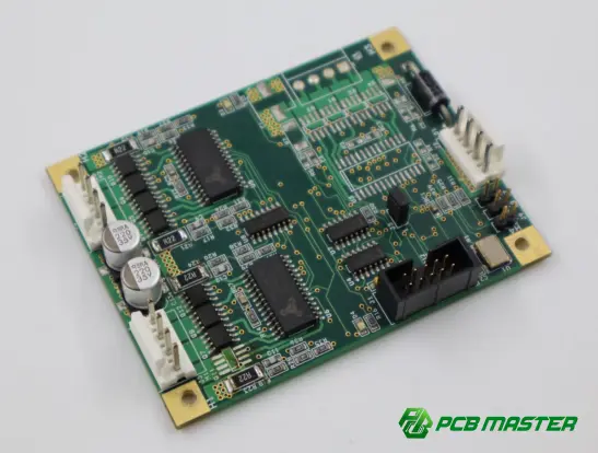
What Is an Inductor?
An inductor is a passive electrical component typically made of a coil of conductive wire wound around an air core or magnetic core. When current flows through the coil, it generates a magnetic field that stores energy. When the current changes, the changing magnetic field induces a voltage that opposes the change in current.
Inductors are widely used in electronic circuits to control current variations, filter unwanted signals, store energy, and suppress electrical noise.
Unlike resistors, which dissipate electrical energy as heat, ideal inductors store energy in their magnetic fields and can return that energy to the circuit. Real inductors, however, have resistance and other losses that convert some energy into heat.
Key Components of an Inductor
An inductor generally consists of the following elements:
- Coil winding: Conductive wire, usually copper, that generates the magnetic field when current flows through it.
- Core: A magnetic or nonmagnetic material that influences inductance, magnetic flux, energy storage, and operating frequency.
- Terminals: Electrical connections that allow the inductor to be mounted on a PCB or connected to other circuit elements.
- Insulation: A dielectric coating or material that electrically separates adjacent wire turns and helps prevent short circuits.
The exact construction depends on the inductor type, rated current, operating frequency, and application requirements.
How Does an Inductor Work?
An inductor operates according to the principle of electromagnetic induction. When the current through its winding changes, the magnetic flux also changes, generating an induced voltage that opposes the current change. This behavior is described by the inductor voltage equation:
V L =L(dI/dt)
Where:
- VL is the voltage across the inductor, measured in volts (V).
- L is the inductance, measured in henries (H).
- dI/dt represents the rate of change of current, measured in amperes per second (A/s).
This equation shows that a higher inductance produces a greater voltage for the same rate of current change.
For example, in a switching power supply, an inductor stores energy while the switching transistor is on and releases energy when the switching state changes. This process helps maintain a more continuous output current and enables efficient voltage conversion.
The energy stored in an ideal inductor is calculated as:
E=(1/2)LI 2
Where E is the stored energy in joules (J), L is inductance, and I is current.
Key takeaway: An inductor resists changes in current rather than opposing current itself. Its behavior depends on inductance, current variation, magnetic properties, and operating conditions.
What Are the Main Types of Inductors?
Inductors can be classified by core material, construction, and intended application. Each type offers different electrical and physical characteristics.
| Inductor type | Core or construction | Main characteristics | Typical applications |
|---|---|---|---|
| Air-core inductor | No magnetic core | Low core loss, suitable for high frequencies | RF circuits, antennas, tuned circuits |
| Iron-core inductor | Iron-based magnetic core | High inductance and magnetic flux capacity | Low-frequency circuits, power equipment |
| Ferrite-core inductor | Ferrite magnetic material | High permeability and useful high-frequency characteristics | Switching power supplies, EMI filters |
| Powdered iron inductor | Distributed-gap magnetic core | Good energy storage and controlled saturation characteristics | DC/DC converters, power inductors |
| Toroidal inductor | Ring-shaped core | Confined magnetic flux and relatively low electromagnetic interference | Power supplies, filters |
| SMD inductor | Surface-mount package | Compact size and automated PCB assembly compatibility | Mobile devices, consumer electronics, embedded systems |
| Coupled inductor | Two or more magnetically coupled windings | Transfers energy or couples signals between windings | Flyback converters, common-mode chokes |
The best choice depends on inductance, rated current, frequency, core losses, available PCB space, and cost.
What Are the Key Electrical Characteristics of an Inductor?
Selecting an inductor requires more than matching its nominal inductance. Engineers must consider its electrical and thermal behavior under actual operating conditions.
Inductance
Inductance measures a component's ability to generate magnetic flux linkage in response to current. It is measured in henries, with millihenries (mH) and microhenries (µH) commonly used in practical circuits.
Higher inductance generally produces a stronger opposition to rapid current changes for a given current variation rate. However, the relationship between inductance and performance depends on circuit topology and operating frequency.
DC Resistance (DCR)
DC resistance is the resistance of the winding to direct current. It causes conduction losses that can be estimated using:
P DCR =I RMS 2 R DCR
A lower DCR generally reduces power dissipation and temperature rise, making it especially important in high-current power applications.
Rated Current and Saturation Current
Two current ratings are particularly important:
- Rated current: Often defined by a specified temperature-rise limit, depending on the manufacturer's test conditions.
- Saturation current: The current at which inductance decreases by a specified amount due to core saturation.
These ratings are not interchangeable. An inductor may exceed its thermal limit before reaching saturation, or it may experience significant inductance reduction before reaching its thermal limit.
Self-Resonant Frequency (SRF)
An inductor has parasitic capacitance between its windings and other conductive structures. Together with inductance, this capacitance creates a self-resonant frequency.
Below SRF, the component generally exhibits inductive behavior. Near SRF, its impedance is strongly affected by resonance and losses. Above SRF, parasitic capacitance can dominate, causing the component to behave more like a capacitor.
Quality Factor (Q)
The quality factor describes the relationship between reactive energy storage and energy loss at a particular frequency. A higher Q generally indicates lower relative losses under the specified measurement conditions.
It is important in RF resonant circuits, filters, and impedance-matching networks.
How Do Inductors Behave at Different Frequencies?
An ideal inductor's inductive reactance is calculated as:
X L =2πfL
Where X L is inductive reactance in ohms (Ω), f is frequency in hertz (Hz), and L is inductance in henries.
As frequency increases, ideal inductive reactance increases proportionally. This makes inductors useful for controlling AC signals and filtering unwanted frequency components.
For example, a 10 µH ideal inductor has the following reactance values:
| Frequency | Inductive reactance |
|---|---|
| 1 kHz | 0.0628 Ω |
| 10 kHz | 0.628 Ω |
| 100 kHz | 6.28 Ω |
| 1 MHz | 62.8 Ω |
These values are theoretical and assume an ideal inductor. Actual impedance depends on winding resistance, core losses, parasitic capacitance, and self-resonance.
Chart suggestion: A line chart of inductive reactance versus frequency for a 10 µH ideal inductor, using a logarithmic frequency axis, can illustrate how reactance increases with frequency.
What Are the Common Applications of Inductors?
Inductors perform several essential functions in modern electronic systems.
Power Conversion
In buck, boost, and other switching converters, inductors store and transfer energy during switching cycles. Their inductance, saturation current, DCR, and thermal performance directly affect current ripple, conversion efficiency, and reliability.
Signal Filtering
Inductors work with capacitors and resistors to form low-pass, high-pass, band-pass, and other filter networks. Their frequency-dependent impedance helps attenuate unwanted signals while preserving desired frequency components.
Electromagnetic Interference Suppression
Inductors and common-mode chokes help suppress conducted electromagnetic interference. They are frequently used in power input filters, communication interfaces, and other circuits where electromagnetic compatibility is important.
RF and Communication Circuits
RF inductors are used in resonant networks, impedance-matching circuits, oscillators, and antenna systems. These applications require careful consideration of Q factor, parasitic capacitance, SRF, and PCB layout.
Automotive and Industrial Electronics
Automotive control units, motor drives, industrial power supplies, and battery management systems use inductors for power conversion, noise suppression, and signal conditioning. Component selection must account for current transients, temperature variation, vibration, and application-specific reliability requirements.
How to Choose the Right Inductor for a PCB Design
Choosing an appropriate inductor requires evaluating the component against the circuit's electrical requirements and the PCB's physical constraints.
| Selection factor | What engineers should evaluate | Why it matters |
|---|---|---|
| Inductance | Nominal value and tolerance | Determines current ripple and frequency response |
| Saturation current | Peak operating current and inductance drop | Prevents excessive inductance reduction |
| RMS current | Thermal rating and actual current waveform | Controls winding temperature rise |
| DCR | Winding resistance at operating temperature | Affects conduction losses and efficiency |
| Operating frequency | Frequency range relative to SRF | Helps maintain the intended electrical behavior |
| Core material | Frequency, flux density, and loss characteristics | Influences efficiency and magnetic performance |
| Package size | Footprint, height, and terminal configuration | Determines PCB placement and assembly compatibility |
| Thermal performance | Copper area, airflow, nearby heat sources | Affects component temperature and long-term reliability |
Common Inductor Selection Mistakes
Choosing inductance based only on its nominal value: Two inductors with the same inductance can have substantially different DCR, saturation current, core losses, and temperature-rise characteristics.
Ignoring peak current: In switching converters, peak inductor current can be significantly higher than average current. The saturation rating must be evaluated against the actual waveform.
Overlooking PCB layout: High-current traces, copper thickness, loop area, thermal paths, and the placement of nearby components influence losses, EMI, and thermal performance.
Using an unsuitable component at high frequencies: Parasitic capacitance and core losses can prevent an inductor from behaving as expected near or above its SRF.
Neglecting manufacturing constraints: Footprint dimensions, pad geometry, component availability, and assembly requirements should be checked before finalizing the PCB design.
How Does PCB Design Affect Inductor Performance?
An inductor's performance depends not only on the component itself but also on its integration into the PCB.
For power circuits, inadequate copper width or an inefficient current path can increase resistance and temperature rise. Large switching-current loops can increase parasitic inductance and radiated EMI. Poor thermal management may also reduce the reliability of nearby components.
Engineers should therefore consider the following practices:
- Place power inductors close to the relevant switching devices and current paths where the circuit topology requires it.
- Minimize high-di/dt loop area to reduce electromagnetic interference.
- Size copper traces and planes according to current, temperature rise, and applicable design requirements.
- Provide suitable thermal paths for high-current inductors.
- Keep sensitive analog or RF circuits away from strong magnetic fields where practical.
- Review the manufacturer's recommended footprint, land pattern, and operating conditions.
For complex power electronics, an engineering review before PCB fabrication can identify potential layout, thermal, and manufacturability issues earlier in the design process.
How PCBMASTER Supports Inductor-Based PCB Projects
For PCB projects involving power conversion, RF circuits, filtering, or EMI suppression, PCB manufacturing quality and engineering support are important parts of the overall design process.
PCBMASTER provides PCB fabrication, PCBA assembly, SMT services, and engineering support for electronic projects ranging from prototypes to production.
Its relevant capabilities include:
- Engineering file review: PCBMASTER offers free engineering document checking to identify potential manufacturability issues and provide optimization suggestions before production.
- Prototype and production support: The company offers rapid PCB prototyping, multilayer PCB fabrication, HDI, high-frequency PCB, flexible PCB, and rigid-flex PCB manufacturing.
- Quality management: PCBMASTER reports operating under ISO 9001 and IATF 16949 quality management systems, with UL certification and RoHS-related compliance claims for applicable products.
- Manufacturing and assembly integration: Its PCB and PCBA services support projects that require board fabrication, component sourcing, and electronic assembly.
For inductor-based designs, engineers should provide complete manufacturing files and clearly communicate relevant requirements, including copper thickness, board stack-up, current-carrying paths, controlled impedance where applicable, and thermal constraints.
These details help the manufacturing team evaluate whether the PCB design can meet the project's electrical, mechanical, and production requirements. Component-level electrical validation remains the responsibility of the design and verification process and should not be inferred solely from PCB manufacturing certifications.
Conclusion
An inductor is a passive component that stores energy in a magnetic field and opposes changes in current. Its behavior is determined by inductance, frequency, winding resistance, core properties, parasitic capacitance, and operating current.
To select the right inductor, engineers should evaluate inductance, saturation current, RMS current, DCR, self-resonant frequency, thermal performance, and PCB layout requirements together rather than relying on a single specification.
As electronic systems become more compact and power-dense, careful coordination between component selection, PCB layout, thermal management, and manufacturing engineering remains essential for achieving reliable circuit performance.
Tags: #Inductor #InductorDescription #Inductance #ElectronicComponents #PCBDesign #PowerElectronics #PCBFabrication #PCBMASTER #EngineeringInsights
About the Author

Carol Luo
PCB Design EngineerI'm Carol, a PCB Engineer at PCBMASTER with experience in PCB design and manufacturing engineering since 2018. I focus on translating engineering requirements into reliable PCB solutions, with expertise in stack-up design, material selection, and design-for-manufacturing (DFM). I share practical engineering insights from real-world PCB design and production experience.
Visit Carol Luo's Profile