








What Is a Variable Inductor? Types, Working Principle, and Applications
A variable inductor is an inductive component whose inductance can be adjusted to control current changes, tune resonant circuits, or optimize electromagnetic performance. Depending on its design, inductance is varied by moving a magnetic core, changing coil geometry, or adjusting magnetic coupling. Variable inductors are used in RF tuning, impedance matching, oscillators, power electronics, and communication equipment. Understanding their types, operating principles, and selection criteria helps engineers design reliable circuits and optimize PCB performance.
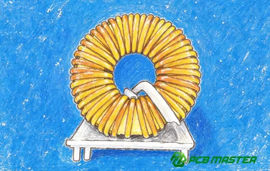
What Is a Variable Inductor?
A variable inductor is a passive electrical component whose inductance can be adjusted over a specified range. Unlike a fixed inductor, which has a nominally constant inductance, a variable inductor allows engineers to modify the magnetic flux linkage and therefore change how the component responds to changing current.
Inductance is measured in henries (H), typically expressed in microhenries (µH) or nanohenries (nH) in RF and electronic circuits.
The inductance of an idealized coil can be expressed as:
L=NΦ/I
Where:
- L is inductance in henries.
- N is the number of coil turns.
- Φ is the magnetic flux through each turn.
- I is the current through the coil.
For a simplified solenoid, inductance is approximately proportional to the core's effective permeability, the square of the number of turns, and the coil's cross-sectional area, and inversely proportional to its length:
L≈μN 2 A/l
Here, μ represents the effective magnetic permeability, A is the cross-sectional area, and l is the magnetic path or coil length under the simplified model's assumptions.
A variable inductor changes one or more parameters affecting inductance, most commonly the effective magnetic permeability or the magnetic coupling between windings.
Key distinction: A variable inductor changes inductance itself. A variable resistor changes resistance, while a variable capacitor changes capacitance. These components may all be used for circuit adjustment, but they affect different electrical characteristics.
How Does a Variable Inductor Work?
The working principle of a variable inductor is based on electromagnetic induction and the relationship between a coil's magnetic field and its inductance.
When current flows through a coil, it generates a magnetic field. If the current changes, the magnetic flux linked with the coil changes, inducing a voltage that opposes the change in current. This behavior follows Faraday's law and Lenz's law.
For an ideal inductor, the voltage-current relationship is:
V=L(dI/dt)
The inductance determines the voltage required to produce a given rate of current change.
1. Adjusting the Magnetic Core
Many variable inductors use a movable ferrite or powdered-iron core. Moving the core into or out of the coil changes the effective permeability of the magnetic circuit and therefore changes inductance.
This mechanism is common in adjustable RF coils and tuning inductors. It enables relatively fine inductance adjustment without changing the number of turns.
2. Changing Coil Geometry
Some designs vary inductance by changing the coil's effective length, spacing, or configuration. These adjustments change magnetic flux linkage and the coil's self-inductance.
Mechanical geometry adjustments are useful in specialized tuning and laboratory applications, although they are less common than movable-core designs in compact electronic equipment.
3. Adjusting Magnetic Coupling
In coupled-coil structures, changing the relative position or spacing of windings changes their mutual inductance. This can alter the effective inductance seen by a circuit, depending on how the windings are connected.
The resulting behavior depends on winding polarity, circuit topology, and the coupling coefficient.
What Happens in an AC Circuit?
An inductor presents inductive reactance to alternating current:
X L =2πfL
Where \(X_L\) is inductive reactance in ohms, \(f\) is frequency in hertz, and \(L\) is inductance in henries.
At a fixed frequency, increasing inductance increases inductive reactance. In an LC resonant circuit, changing inductance also shifts the resonant frequency:
f 0 =1/[2π(LC) 1/2 ]
This relationship explains why variable inductors are useful for tuning radio-frequency circuits and adjusting resonant networks.
What Are the Main Types of Variable Inductors?
Variable inductors can be classified by their adjustment mechanism, magnetic structure, and method of control. The most common practical design uses a movable magnetic core, while other designs change the coil geometry, magnetic coupling, or active electrical configuration.
1. Ferrite-Core Variable Inductors
Ferrite-core variable inductors use a threaded or sliding ferrite core positioned inside a winding. Adjusting the core changes the effective magnetic permeability and inductance.
- Advantages: Compact construction, practical adjustment range, and suitability for RF tuning.
- Limitations: Core losses, magnetic saturation, mechanical adjustment sensitivity, and temperature-dependent characteristics.
- Applications: RF amplifiers, oscillator circuits, receiver tuning, and impedance-matching networks.
This type is useful when engineers need to calibrate an inductance value during circuit development or production.
2. Air-Core Variable Inductors
Air-core variable inductors use air rather than a ferrite or iron core as the primary magnetic medium. Inductance can be adjusted by changing the effective number of turns, winding geometry, or relative position of coupled coils.
- Advantages: Avoids magnetic-core saturation and can provide favorable high-frequency characteristics.
- Limitations: Often requires more physical space, and the magnetic field may be less confined than in a shielded core design.
- Applications: RF tuning equipment, antenna tuners, transmitters, and specialized high-frequency circuits.
Roller-coil designs are one example: a movable contact changes the effective length of the winding connected to the circuit.
3. Powdered-Iron-Core Variable Inductors
Powdered-iron-core designs use magnetic particles dispersed in an insulating binder. Their magnetic properties depend on the material formulation, core geometry, and operating conditions.
- Advantages: Core properties can be tailored for particular frequency and loss requirements.
- Limitations: Core losses, temperature behavior, and saturation characteristics must be evaluated for the intended application.
- Applications: Selected RF circuits, tuning networks, and adjustable inductive components.
Powdered-iron and ferrite cores are not interchangeable by default. Their permeability, loss characteristics, and frequency-dependent behavior differ, so selection should be based on the component's electrical specifications.
4. Variometers
A variometer changes effective inductance by rotating or repositioning one coil relative to another. Depending on the coil arrangement and winding polarity, the mutual inductance can increase or decrease the total effective inductance.
- Advantages: Provides a continuously adjustable inductive response in suitable designs.
- Limitations: Mechanical complexity, size, and coupling sensitivity.
- Applications: Specialized radio-frequency equipment, antenna systems, and historical or laboratory tuning circuits.
5. Electronically Tunable Inductors
Electronically tunable inductors adjust effective inductance or inductive impedance through switched coil paths, variable coupling, MEMS structures, or active semiconductor circuits. Some implementations offer discrete settings; others provide continuous tuning.
- Advantages: Enables remote control, automation, and integration into reconfigurable electronic systems.
- Limitations: Design complexity, control requirements, parasitic effects, and potential trade-offs in quality factor and linearity.
- Applications: Reconfigurable RF front ends, wireless communication systems, and specialized integrated circuits.
An important distinction is that a varactor-tuned LC circuit is not necessarily a variable inductor: a varactor changes capacitance while the inductor may remain fixed. The circuit's resonant frequency changes, but the inductance itself does not.
Variable Inductor Types Compared
| Type | Adjustment mechanism | Main advantage | Typical application |
|---|---|---|---|
| Ferrite-core | Move or rotate magnetic core | Compact, practical tuning | RF receivers and oscillators |
| Air-core | Change turns or coil geometry | No magnetic-core saturation | RF transmitters and antenna tuners |
| Powdered-iron-core | Adjust core position or configuration | Tailorable magnetic properties | Selected RF tuning circuits |
| Variometer | Change coupling between coils | Adjustable effective inductance | Specialized RF systems |
| Electronic tuning | Switch coil paths, coupling, or active elements | Remote or automated control | Reconfigurable RF systems |
Selection principle: The best variable inductor is not necessarily the one with the widest adjustment range. It must also meet the application's frequency, Q-factor, current, thermal, mechanical, and stability requirements.
What Are the Main Applications of Variable Inductors?
Variable inductors are especially useful when a circuit must accommodate different operating frequencies, compensate for component tolerances, or adjust its impedance response. Their role is most apparent in tuned RF networks, although their use extends to specialized instrumentation and power-related circuits.
1. Radio-Frequency Tuning
In radio receivers and transmitters, a variable inductor can adjust an LC resonant circuit to a target frequency. This allows the circuit to select a desired frequency band or calibrate a signal-processing stage.
Engineers must consider the tuning range, resonant frequency, unloaded Q, and parasitic capacitance when designing the circuit.
2. Impedance Matching
Impedance-matching networks help transfer power between a source and a load while controlling reflections. A variable inductor can adjust the network's reactive impedance to accommodate changes in operating frequency or load conditions.
Applications include antenna matching networks, RF amplifiers, and selected transmitter output stages.
3. Oscillators and Frequency-Generation Circuits
An LC oscillator uses an inductive-capacitive network to establish its nominal oscillation frequency. Adjusting the inductance changes the resonant frequency, provided the circuit's other operating conditions remain suitable.
Variable inductors can be used for calibration and tuning, although electronically controlled frequency generation often uses alternative architectures where size, speed, repeatability, or integration is a priority.
4. Adjustable Filters
Variable inductors can change the center frequency or frequency response of resonant filters. This is useful in equipment that requires calibration or operation across a range of frequencies.
However, changing inductance can also affect filter bandwidth, insertion loss, and impedance. These parameters must be evaluated together rather than optimizing center frequency alone.
5. Test and Measurement Equipment
Laboratory instruments and specialized calibration systems may use adjustable inductors to tune resonant circuits, compensate for tolerances, or evaluate circuit behavior across different conditions.
In such applications, adjustment resolution, repeatability, drift, and measurement uncertainty are important selection criteria.
6. Power and Control Electronics
Variable inductors can be used in specialized power-electronic and reactive-compensation systems where adjustable inductive behavior is required. They are not, however, the default solution for most compact switching power supplies.
In many modern converters, fixed power inductors are preferred because they provide predictable performance, efficient energy storage, and straightforward manufacturing. Adjustable designs are justified when their tuning capability solves a specific system-level problem.
What Factors Should You Consider When Selecting a Variable Inductor?
Selecting a variable inductor requires more than matching the nominal inductance. Engineers should evaluate the complete operating range and the interaction between the component, circuit, and PCB layout.
1. Inductance Range and Adjustment Resolution
Determine the minimum and maximum inductance required by the circuit. Then verify that the component provides adequate adjustment resolution across that range.
A wide nominal tuning range is not sufficient if the required operating point is difficult to set accurately or changes significantly with temperature.
2. Operating Frequency and Quality Factor
The quality factor, or Q, indicates the ratio of inductive reactance to effective series resistance for a simplified inductor model:
Q=2πfL/R s
Where R s represents the effective series resistance at the operating frequency.
A higher Q generally means lower relative resistive loss, which can benefit resonant circuits and RF matching networks. However, Q varies with frequency, core material, construction, and parasitic effects. It should be evaluated at the actual operating frequency rather than treated as a fixed component property.
3. Current Rating and Magnetic Saturation
For power-related applications, check the rated current, winding temperature rise, and saturation characteristics.
As magnetic materials approach saturation, their effective permeability can decrease, causing inductance to change with current. This may affect ripple current, electromagnetic interference (EMI) , and circuit stability.
The relevant limits depend on the specific component and its thermal environment.
4. Temperature Stability and Mechanical Reliability
Inductance may vary with temperature because of changes in magnetic permeability, winding dimensions, and material properties. Mechanically adjustable components can also be sensitive to vibration, shock, and adjustment mechanisms loosening over time.
For automotive, industrial, or other demanding applications, evaluate the specified operating temperature range, mechanical robustness, and long-term stability.
5. PCB Layout and Electromagnetic Compatibility
The PCB layout can influence the performance of a variable inductor, particularly in high-frequency circuits.
Important considerations include:
- Placement: Keep RF inductors close to the circuit nodes they serve to minimize unwanted interconnect inductance.
- Grounding: Follow the circuit topology and component manufacturer's recommendations for ground-plane configuration and return paths.
- Coupling: Maintain appropriate spacing between inductors and other magnetic components to reduce unwanted coupling.
- Parasitics: Account for PCB trace inductance, pad capacitance, nearby copper, and the component's self-resonant frequency.
- Thermal management: Ensure that copper geometry and nearby heat sources do not compromise component temperature limits.
For RF circuits, even small parasitic effects can shift the tuned response. Therefore, the final inductance adjustment should be verified on the assembled board under representative operating conditions.
Variable Inductor vs. Fixed Inductor: What Is the Difference?
Both components store energy in a magnetic field, but they serve different design priorities.
| Comparison | Variable inductor | Fixed inductor |
|---|---|---|
| Inductance | Adjustable within a specified range | Nominally fixed |
| Main purpose | Tuning and calibration | Stable, predetermined inductance |
| Construction | May include a movable core or adjustment mechanism | Usually optimized for a defined value |
| Circuit design | Requires consideration of the adjustment range | Generally simpler to specify and integrate |
| Manufacturing | May require additional adjustment or calibration | Often easier to automate in high-volume assembly |
| Common use | Tuned RF circuits and specialized adjustable networks | Power supplies, filters, RF matching, and general electronics |
Which should you choose?
Choose a variable inductor when the circuit genuinely needs adjustable inductance, such as for RF alignment or compensation. Choose a fixed inductor when the required value is known and stability, repeatability, compactness, or automated assembly takes priority.
In many modern electronic products, a fixed inductor combined with a switched capacitor bank or another tuning mechanism can be more practical than a mechanically adjustable inductor. The correct solution depends on the required tuning range, loss, control method, and manufacturing constraints.
Common Variable Inductor Design and Selection Mistakes
Even a correctly specified component can underperform if the surrounding circuit is not designed appropriately.
Mistake 1: Selecting a Component Based Only on Nominal Inductance
Two inductors with the same nominal inductance can have different Q factors, self-resonant frequencies, current limits, and temperature characteristics.
Better approach: Compare the complete datasheets at the intended operating frequency and current.
Mistake 2: Ignoring Parasitic Capacitance
An inductor has parasitic capacitance between its turns and to nearby conductive structures. Above its self-resonant frequency, its behavior may no longer resemble that of an ideal inductor.
Better approach: Verify that the component's self-resonant frequency and measured impedance characteristics are suitable for the circuit's operating band.
Mistake 3: Assuming a Variable Inductor Automatically Improves Tuning Performance
A wider adjustment range does not guarantee better frequency stability or lower insertion loss. Core losses, mechanical tolerances, and circuit parasitics can reduce performance.
Better approach: Define the required tuning range, Q, stability, and repeatability before choosing a component.
Mistake 4: Ignoring PCB Manufacturing Constraints
The selected inductor must fit the intended footprint, assembly process, and board-level electrical requirements. Placement and copper geometry can also influence high-frequency performance.
Better approach: Complete schematic review, PCB layout verification, and engineering checks before production.
How PCB Manufacturing Supports Variable Inductor Circuit Performance
Variable inductors are components integrated into a broader electronic design. Their performance depends not only on the component itself but also on the surrounding circuit, PCB layout, assembly quality, and verification process.
For products incorporating adjustable RF circuits, engineers should review component footprints, signal paths, grounding, impedance requirements, and electromagnetic coupling before releasing the board for manufacturing.
PCBMASTER's Engineering and Manufacturing Approach
As a PCB and PCBA service provider, PCBMASTER supports electronic projects that incorporate inductors and other passive components through PCB fabrication, assembly, and engineering file review.
Its relevant capabilities include:
- Engineering file review: PCBMASTER provides engineering document checks intended to identify manufacturability concerns and potential design optimization opportunities before production.
- PCB and PCBA services: Integrated fabrication and assembly services help customers coordinate board production and component integration.
- Quality management: PCBMASTER reports operating under ISO 9001 and IATF 16949 quality management systems, with UL certification and RoHS-related compliance claims subject to the applicable product and documentation scope.
- Prototype and production support: Rapid prototyping and production services support development from initial board validation through manufacturing scale-up.
For a PCB incorporating a variable inductor, engineering review should focus on the actual design requirements. RF projects may require additional impedance analysis, electromagnetic simulation, or laboratory measurements; a standard manufacturability review alone does not establish RF performance.
PCBMASTER's role is to support the manufacture and assembly of the board, while the final electrical performance must be verified against the product's design specifications.
Conclusion: How to Choose the Right Variable Inductor
A variable inductor provides adjustable inductance for circuits that require frequency tuning, impedance matching, calibration, or specialized reactive control. The principal types include ferrite-core, air-core, powdered-iron-core, variometer, and electronically tunable designs.
The most appropriate choice depends on five primary factors:
- Required inductance range and tuning resolution.
- Operating frequency and Q factor.
- Current handling and magnetic saturation.
- Temperature stability and mechanical reliability.
- PCB layout, parasitic effects, and manufacturing requirements.
The most effective design process begins with clearly defined electrical requirements, followed by component selection, circuit simulation, PCB layout verification, and testing of the assembled product.
For engineers developing electronic products, treating the variable inductor as part of the complete circuit and PCB system—not as an isolated component—is essential to achieving reliable and repeatable performance.
Tags: #VariableInductor #Inductors #ElectronicsEngineering #RFCircuitDesign #ImpedanceMatching #PCBDesign #PCBA #PCBMASTER #EngineeringInsights
About the Author

Carol Luo
PCB Design EngineerI'm Carol, a PCB Engineer at PCBMASTER with experience in PCB design and manufacturing engineering since 2018. I focus on translating engineering requirements into reliable PCB solutions, with expertise in stack-up design, material selection, and design-for-manufacturing (DFM). I share practical engineering insights from real-world PCB design and production experience.
Visit Carol Luo's Profile