








Symbol for an Inductor: Circuit Symbol, Function, and PCB Applications
The symbol for an inductor in an electrical circuit diagram represents a passive component that stores energy in a magnetic field when electric current flows through it. Its standard schematic symbol resembles a series of curved loops or a coil. Inductors are widely used in PCB design, power management, signal filtering, and electromagnetic interference (EMI) suppression. Understanding the inductor symbol helps engineers read circuit diagrams, identify components, and design reliable electronic circuits.
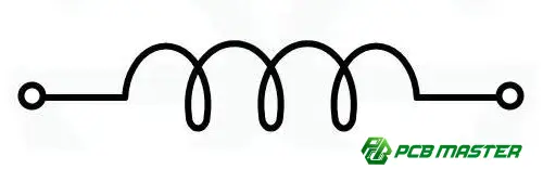
What Is the Symbol for an Inductor?
The standard circuit symbol for an inductor resembles a coil, typically drawn as several curved loops between two terminals. It represents the component's ability to store energy in a magnetic field and oppose changes in current.
A basic inductor symbol can be represented using this simplified text illustration:
───((((((───
The exact appearance varies depending on the schematic standard, drawing software, and inductor type. Some symbols use semicircular loops, while others use rectangular or more stylized coil shapes.
In circuit diagrams, the letter L is commonly used as the reference designator for an inductor. For example, L1, L2, and L3 identify individual inductors in a circuit.
Common Types of Inductor Symbols
Different inductor constructions may use variations of the basic coil symbol to indicate their physical characteristics.
| Inductor type | Symbol characteristics | Typical applications |
|---|---|---|
| Air-core inductor | Coil without a core marking | RF circuits, high-frequency applications |
| Iron-core inductor | Coil with core lines or a core indication | Power conversion, filtering |
| Ferrite-core inductor | Coil with core markings, depending on the schematic convention | EMI suppression, switching power supplies |
| Variable inductor | Coil with a diagonal arrow | Tunable RF circuits, impedance matching |
| Coupled inductors | Two coils with core or coupling markings | Flyback converters, transformers, coupled power circuits |
Note: Symbol conventions can vary between schematic libraries and standards. Always check the component legend or applicable schematic standard when interpreting a specialized symbol.
What Does an Inductor Do in a Circuit?
An inductor is a passive electrical component that stores energy in a magnetic field. Its behavior is described by the relationship between inductance, current, and voltage.
The voltage across an ideal inductor is expressed as:
V=L(dI/dt)
Where:
- V is the voltage across the inductor.
- L is the inductance, measured in henries (H).
- dI/dt is the rate of change of current over time.
This relationship means that an inductor opposes changes in current. Its practical behavior depends on frequency, winding resistance, core material, and other electrical characteristics.
Key Functions of Inductors
1. Energy storage
Inductors store energy in their magnetic fields and release it as circuit conditions change. This is particularly important in switching regulators and DC-DC converters.
2. Signal filtering
Inductors work with capacitors and resistors to form filters that attenuate unwanted frequency components while allowing desired signals to pass.
3. EMI suppression
Ferrite beads and other inductive components help reduce high-frequency noise in electronic circuits, depending on their impedance characteristics and placement.
4. Current smoothing
Inductors reduce current ripple in switching power supplies, helping deliver more stable current to electronic loads.
How to Identify an Inductor in a PCB Schematic
When reading a PCB schematic, use the following steps to distinguish an inductor from other components.
- Look for the coil-shaped symbol. A series of loops usually indicates an inductor.
- Check the reference designator. The letter L, as in L1 or L5, generally identifies an inductor.
- Review the component value. Inductance is commonly specified in µH (microhenries), mH (millihenries), or nH (nanohenries).
- Examine the surrounding circuit. Inductors often appear near switching ICs, power supply inputs, filters, or RF matching networks.
- Verify the bill of materials (BOM). The BOM provides the part number, inductance, current rating, and other specifications needed to identify the actual component.
Inductor vs. Resistor vs. Capacitor Symbols
| Component | Common reference designator | Typical schematic appearance | Main function |
|---|---|---|---|
| Inductor | L | Coil or loops | Stores magnetic energy and opposes changes in current |
| Resistor | R | Zigzag line or rectangle | Limits current and dissipates energy |
| Capacitor | C | Two parallel plates | Stores energy in an electric field |
Inductor Applications in PCB Design
Inductors are important in many PCB applications, especially where power conversion, signal integrity, and electromagnetic compatibility are critical.
Power Management
In buck and boost converters, inductors transfer and store energy during switching cycles. Engineers must select appropriate inductance, saturation current, RMS current rating, and DC resistance to meet the converter's performance requirements.
RF and High-Frequency Circuits
Inductors are used in impedance-matching networks, resonant circuits, and RF filters. Their self-resonant frequency, quality factor, and parasitic effects can influence high-frequency performance.
EMI and Noise Filtering
Inductors and ferrite components can suppress unwanted noise on power and signal lines. Their effectiveness depends on frequency, circuit impedance, layout, and the characteristics of the noise source.
PCB Layout Considerations
When placing inductors on a PCB, engineers should consider:
- Current capacity: Ensure that the component can handle the expected operating and peak currents.
- Magnetic coupling: Maintain appropriate spacing between inductors and noise-sensitive circuits when necessary.
- Trace geometry: Minimize high-current loop area in switching power supply layouts.
- Thermal management: Account for copper losses, core losses, and nearby heat sources.
- Component verification: Match the schematic, PCB footprint, BOM, and manufacturer's datasheet.
For custom PCB and PCBA projects, these details should be reviewed during engineering design and design-for-manufacturability (DFM) checks.
How PCBMASTER Supports PCB Manufacturing and Assembly
Selecting the correct inductor symbol is only the first step. Successful hardware development also requires accurate schematics, verified footprints, suitable component specifications, and a manufacturable PCB layout.
PCBMASTER provides PCB fabrication and PCBA services , including engineering file review, component sourcing, assembly, and testing. Its engineering support can help customers review manufacturing files and identify potential issues before production.
For projects involving power electronics, RF circuits, or other specialized PCB designs, engineers should confirm that component requirements, board construction, and assembly specifications are aligned before placing a production order.
Frequently Asked Questions
What is the letter symbol for an inductor?
The standard reference designator for an inductor is L. For example, L1 identifies the first inductor in a schematic.
What is the unit of an inductor?
Inductance is measured in henries (H). Common practical units include millihenries (mH), microhenries (µH), and nanohenries (nH).
Is an inductor symbol the same as a coil symbol?
In many electrical schematics, an inductor is represented by a coil-shaped symbol. However, not every coil symbol necessarily represents a standalone inductor; context and the applicable schematic convention matter.
How can I distinguish an inductor from a transformer?
An inductor is generally represented by one coil. A transformer typically uses two or more coupled coils, often with core markings between them.
Does an inductor have polarity?
A conventional fixed inductor is generally non-polarized, meaning its two terminals can usually be connected in either direction. However, some specialized components or circuit configurations may have orientation or pin-assignment requirements.
Conclusion
The symbol for an inductor is typically a coil-shaped mark, and its reference designator is the letter L. Recognizing this symbol helps engineers interpret schematics, understand filtering and power conversion circuits, and identify the components needed for PCB manufacturing and assembly.
When designing a PCB, symbol recognition should be accompanied by careful component selection, footprint verification, and layout review to support reliable electrical performance.
Tags: #InductorSymbol #Inductor #CircuitSymbols #PCBDesign #ElectronicsEngineering #PCBA #PCBMASTER #ElectronicsDesign
About the Author

Carol Luo
PCB Design EngineerI'm Carol, a PCB Engineer at PCBMASTER with experience in PCB design and manufacturing engineering since 2018. I focus on translating engineering requirements into reliable PCB solutions, with expertise in stack-up design, material selection, and design-for-manufacturing (DFM). I share practical engineering insights from real-world PCB design and production experience.
Visit Carol Luo's Profile

