








Inductor Calculator: Formulas, Design Methods, and Practical Applications
An inductor calculator helps engineers determine inductance, inductive reactance, stored energy, resonant frequency, and other parameters required for electronic circuit design. By applying the correct formulas and electrical specifications, engineers can select suitable inductors for DC/DC converters, filters, oscillators, and RF circuits. Understanding the relationship between inductance, frequency, current, and magnetic saturation is essential for reliable circuit performance. For PCB and PCBA projects, accurate inductor calculations also support component selection, thermal management, and power-stage optimization.
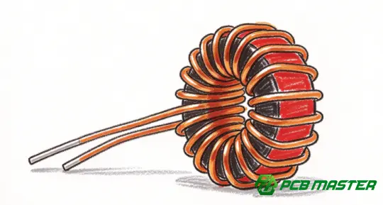
What Is an Inductor Calculator?
An inductor calculator is an engineering tool used to calculate electrical and magnetic parameters associated with inductors. It applies established circuit equations to convert known values into useful design parameters, reducing manual calculations and helping engineers evaluate component suitability.
An inductor stores energy in a magnetic field when current flows through its winding. Its behavior depends on inductance, current variation, operating frequency, winding resistance, core material, and circuit topology.
Depending on the intended application, an inductor calculator can help determine:
- Inductance: The inductance required to achieve a specified electrical response.
- Inductive reactance: The opposition an inductor presents to alternating current at a given frequency.
- Stored energy: The magnetic energy stored at a particular current.
- Resonant frequency: The resonant frequency of an LC circuit.
- Inductor current ripple: The current variation in switching power converters.
- Inductance from impedance: The inductance corresponding to a measured impedance under specified conditions.
These calculations are useful during schematic design, component selection, circuit simulation, PCB layout, and hardware verification.
Essential Inductor Calculator Formulas
The correct formula depends on the electrical parameter being calculated and the operating conditions of the circuit.
| Calculation | Formula | Purpose |
|---|---|---|
| Inductance | L=V L △t/△I | Estimate inductance from voltage and current change |
| Inductive reactance | X L =2πfL | Determine AC reactance |
| Stored energy | E=(1/2)LI 2 | Calculate magnetic energy |
| LC resonant frequency | f 0 =1/[2π(LC) 1/2 ] | Determine ideal resonance |
| Inductor voltage | V L =L(dI/dt) | Relate voltage to current change |
| Inductor impedance | Z L =j2πfL | Describe ideal inductor impedance in AC analysis |
Where:
- L = inductance in henries (H)
- VL = voltage across the inductor in volts (V)
- △t = time interval in seconds (s)
- △I = current change in amperes (A)
- f = frequency in hertz (Hz)
- XL= inductive reactance in ohms (Ω)
- E = stored energy in joules (J)
- C = capacitance in farads (F)
- j = imaginary unit
Important: The formula L=X L △t/△Iassumes an approximately constant inductor voltage over the measurement interval. In switching converters, use the actual voltage across the inductor during the relevant switching interval.
How to Calculate Inductance
Inductance can be calculated from voltage and current measurements or determined from a circuit's required electrical response.
1. Calculate Inductance from Voltage and Current
For an ideal inductor, the voltage-current relationship is:
V L =L(dI/dt)
Rearranging for approximately constant voltage gives:
L=V L △t/△I
For example, suppose an inductor experiences 5 V across its terminals for 10 μs, and its current increases by 0.5 A during that interval.
L=(5×10×10 -6 )/0.5=100μH
The calculated inductance is 100 μH.
This method is particularly useful when evaluating inductors in switching power supplies. However, the voltage used must be the actual voltage across the inductor, not simply the input voltage or output voltage.
2. Calculate Inductance from Inductive Reactance
Inductive reactance increases with both inductance and frequency.
The formula is:
X L =2πfL
Rearranging:
L=X L /(2πf)
Suppose an inductor has a reactance of 62.83 Ω at 100 kHz.
L=62.83/(2π×100000)≈100μH
The corresponding ideal inductance is approximately 100 μH.
This calculation is useful for AC circuits, filter design, and impedance analysis. For real components, measured impedance may also include winding resistance, parasitic capacitance, and core losses.
3. Calculate Inductance from Stored Energy
An inductor stores energy in its magnetic field according to:
E=(1/2)LI 2
Rearranging for inductance:
L=2E/I 2
If a circuit requires an inductor to store 2 mJ of energy at a current of 2 A:
L=2×0.002/2 2 =1mH
The theoretical inductance is 1 mH.
This calculation is relevant to energy-storage applications, but it does not establish whether the selected component can withstand the required current without saturation or excessive heating.
Inductive Reactance Calculator: Understanding Frequency Effects
Inductive reactance describes the opposition an ideal inductor presents to alternating current. Unlike an ideal resistor, an inductor's reactance varies with frequency.
X L =2πfL
Consider a 10 μH inductor operating at different frequencies.
| Frequency | Inductive reactance |
|---|---|
| 1 kHz | 0.0628 Ω |
| 10 kHz | 0.628 Ω |
| 100 kHz | 6.28 Ω |
| 1 MHz | 62.83 Ω |
As frequency increases, inductive reactance increases proportionally, provided the inductance remains approximately constant.
This relationship is important when designing:
- Low-pass and high-pass filters
- Switching power supplies
- EMI suppression networks
- RF matching circuits
- Oscillators and resonant circuits
However, real inductors do not behave ideally at all frequencies. Above their self-resonant frequency, parasitic capacitance can dominate their behavior. Engineers should therefore consult the manufacturer's impedance, inductance, and self-resonant-frequency specifications when selecting high-frequency components.
LC Resonant Frequency Calculator
An LC circuit consists of an inductor and capacitor. Its ideal resonant frequency is determined by their inductance and capacitance.
f 0 =1/[2π(LC) 1/2 ]
To calculate the resonant frequency, use inductance in henries and capacitance in farads.
For example, consider an LC circuit with:
- Inductance: 10 μH
- Capacitance: 100 nF
Substituting these values:
f 0 =1/[2π(10×10 -6 ×100×10 -9 ) 1/2 ]
The resulting resonant frequency is approximately 159.2 kHz.
The calculation provides an ideal starting point for resonant converters, tuned filters, and RF circuits. Actual resonance can differ because of component tolerances, parasitic capacitance, winding resistance, PCB parasitics, and loading.
Inductor Calculator for DC/DC Converter Design
Inductor calculations are especially important in buck, boost, and other switching DC/DC converters. The inductance affects current ripple, transient response, magnetic component size, and overall converter performance.
Buck Converter Inductance
For an ideal buck converter operating in continuous conduction mode, the inductor current ripple can be estimated using:
△I L =(V i n -V out )D/(Lf s )
Where:
V i n = input voltage
V out = output voltage
D = duty cycle
L = inductance
f s = switching frequency
For an ideal buck converter:
D≈V out /V i n
Rearranging the ripple equation gives:
L=(V i n -V out )D/(△I L f s )
Consider a converter with the following design parameters:
| Parameter | Value |
|---|---|
| Input voltage | 12 V |
| Output voltage | 5 V |
| Duty cycle | 0.417 |
| Switching frequency | 500 kHz |
| Target peak-to-peak ripple | 0.5 A |
The estimated inductance is:
L=(12-5)×0.417/(0.5×500000)≈11.68μH
A nominal inductance around 12 μH may be a reasonable starting point for component evaluation.
The calculation alone does not finalize the component selection. The designer must also verify peak current, saturation current, RMS current rating, DC resistance, core losses, temperature rise, and performance over the full input and load range.
Boost Converter Inductance
For an ideal boost converter operating in continuous conduction mode, the approximate inductor current ripple is:
△I L =V i n D/(Lf s )
Therefore:
L=V i n D/(△I L f s )
The duty cycle for an ideal boost converter is approximately:
D=1-V i n /V out
These equations provide a preliminary estimate. Practical designs must account for converter losses, operating-mode transitions, component tolerances, and control-loop requirements.
Common Inductor Calculation Errors
Even when the correct formula is used, incorrect assumptions or unit conversions can lead to unsuitable component choices.
Mixing Inductance Units
Inductance is commonly expressed in henries, millihenries, and microhenries.
| Unit | Equivalent value |
|---|---|
| 1 H | 1 H |
| 1 mH | 0.001 H |
| 1 μH | 0.000001 H |
| 1 nH | 0.000000001 H |
Convert all values to consistent units before substituting them into equations. A microhenry-to-henry conversion error can produce a result that differs by a factor of one million.
Ignoring Saturation Current
An inductor's effective inductance can decrease as current approaches its saturation region. This is especially important in power converters, where peak current may significantly exceed average current.
A useful first-order estimate for peak inductor current is:
I peak =I avg +△I L /2
For example, if average current is 3 A and peak-to-peak ripple is 0.8 A, the estimated peak current is 3.4 A.
The selected component must support this current with appropriate margin under the manufacturer's specified saturation and thermal conditions.
Treating Ideal Inductance as Constant at Every Frequency
Real inductors have parasitic capacitance, winding resistance, and frequency-dependent core losses. Near self-resonance, their impedance behavior can differ significantly from the ideal inductive model.
For high-frequency circuits, engineers should verify the component's impedance-versus-frequency curve and self-resonant frequency.
Ignoring PCB Layout and Thermal Effects
The selected inductor interacts with the PCB's copper geometry, switching-node layout, nearby components, and thermal environment.
Poor layout can increase electromagnetic interference, parasitic inductance, and switching losses. In power-conversion circuits, short high-current paths, suitable copper width, effective thermal management, and appropriate component placement are important design considerations.
Practical Inductor Selection for PCB and PCBA Projects
An inductor calculator supports component selection, but a successful design also requires engineering evaluation of the complete circuit and manufacturing constraints.
Before finalizing an inductor, verify the following:
- Inductance and tolerance: Confirm that the nominal value and tolerance meet the circuit requirements.
- Current ratings: Evaluate saturation current, RMS current, and peak operating current.
- DC resistance: Check winding losses and their effect on efficiency and temperature rise.
- Frequency response: Confirm that the operating frequency is compatible with the component's characteristics.
- Physical dimensions: Verify footprint, component height, pad geometry, and assembly clearances.
- Thermal performance: Assess power dissipation, airflow, copper area, and surrounding heat sources.
- EMI performance: Evaluate magnetic-field coupling, switching-loop geometry, and the placement of sensitive signals.
- Manufacturing compatibility: Confirm component availability, soldering requirements, footprint accuracy, and assembly process compatibility.
For PCB and PCBA projects, these checks help prevent issues that may not be apparent from an inductance calculation alone.
PCBMASTER provides PCB fabrication, PCBA assembly, SMT services, and engineering file review. For projects involving inductors in switching power supplies, filters, or other electronic circuits, manufacturability review can help identify footprint, spacing, and layout concerns before production. Final electrical performance must still be validated through appropriate circuit analysis and hardware testing.
Frequently Asked Questions About Inductor Calculators
1. How do you calculate inductance?
For an approximately constant voltage across an ideal inductor, calculate inductance using L=V L △t/△I. Alternatively, use reactance and frequency, or stored energy and current, when those parameters are known.
2. What is the formula for inductive reactance?
The formula is X L =2πfL, where f is frequency and L is inductance. The result is expressed in ohms.
3. How do you calculate the resonant frequency of an LC circuit?
Use f 0 =1/[2π(LC) 1/2 ]. This gives the ideal resonant frequency of an LC circuit, assuming the inductance and capacitance are known.
4. How do you calculate the energy stored in an inductor?
Use E=(1/2)LI 2 . Energy increases linearly with inductance and with the square of current.
5. How do you choose an inductor for a buck converter?
Calculate the required inductance from input voltage, output voltage, switching frequency, duty cycle, and target current ripple. Then verify saturation current, RMS current, winding resistance, thermal performance, and component tolerances.
6. Can an inductor calculator determine the exact inductance of a real component?
It can calculate an estimated value from known electrical parameters. Actual inductance may vary with frequency, current, temperature, core characteristics, and measurement conditions. Use an appropriate instrument or impedance analyzer when accurate measurement is required.
7. Why does inductive reactance increase with frequency?
For an ideal inductor, reactance is proportional to frequency. As frequency rises, the voltage required to produce a given sinusoidal current increases. Real components may depart from this relationship near their self-resonant frequency.
8. What is the difference between inductance and impedance?
Inductance is a component parameter measured in henries. Impedance describes the total opposition to alternating current, incorporating resistance and reactance, and is measured in ohms.
9. How does inductor saturation affect a circuit?
As the magnetic core approaches saturation, inductance can decrease, causing current to rise more rapidly than expected. This may increase losses, generate excess heat, and compromise power-converter operation.
10. Why does PCB layout matter when using inductors?
PCB layout affects parasitic inductance, electromagnetic interference, current-loop area, heat dissipation, and coupling to nearby circuits. Careful placement and routing are especially important in switching power supplies and high-frequency designs.
Conclusion
An inductor calculator provides a practical foundation for evaluating inductance, reactance, stored energy, resonant frequency, and switching-converter current ripple. However, reliable component selection requires more than a mathematical result.
Engineers should combine calculations with datasheet verification, saturation and thermal analysis, frequency-response evaluation, and PCB layout review. This approach improves the likelihood that the selected inductor will meet electrical, thermal, and manufacturing requirements throughout the intended operating range.
Tags: #InductorCalculator #Inductance #InductiveReactance #PowerElectronics #DCDCConverter #PCBDesign #PCBA #PCBMASTER
About the Author

Carol Luo
PCB Design EngineerI'm Carol, a PCB Engineer at PCBMASTER with experience in PCB design and manufacturing engineering since 2018. I focus on translating engineering requirements into reliable PCB solutions, with expertise in stack-up design, material selection, and design-for-manufacturing (DFM). I share practical engineering insights from real-world PCB design and production experience.
Visit Carol Luo's Profile