








Common Capacitor Values: Standard Capacitance Values, Codes, and Selection Guide
Common capacitor values follow standardized preferred-value series, making it easier for engineers to select practical capacitance values for circuit design and PCB assembly. Frequently used values include 1 pF, 10 pF, 100 pF, 1 nF, 10 nF, 100 nF, 1 µF, 10 µF, and 100 µF , although the appropriate value depends on the circuit function, voltage rating, tolerance, capacitor type, frequency, and available package. Understanding capacitor value codes and standard E-series values helps engineers select components efficiently and design PCBs for reliable manufacturing.
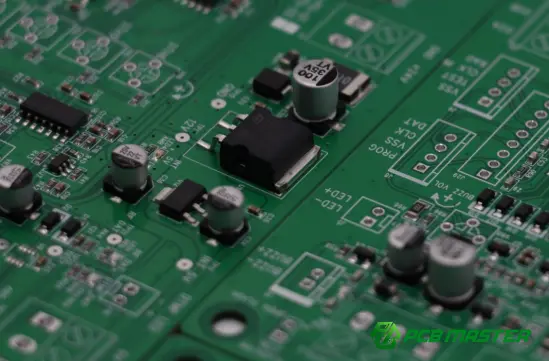
What Are Common Capacitor Values?
A capacitor's capacitance indicates its ability to store electrical charge and is measured in farads (F) . Because one farad is extremely large for most electronic circuits, practical capacitor values are commonly expressed in:
- pF — picofarads (10⁻¹² F)
- nF — nanofarads (10⁻⁹ F)
- µF — microfarads (10⁻⁶ F)
- mF — millifarads (10⁻³ F)
In practical electronics, capacitor values span several orders of magnitude. Small ceramic capacitors used for RF and high-frequency circuits may have values of only a few picofarads, while power-supply filtering can require tens, hundreds, or thousands of microfarads.
Some of the most commonly encountered nominal values include:
| Capacitance | Typical Unit | Common Applications |
|---|---|---|
| 1 pF | pF | RF tuning, matching |
| 10 pF | pF | RF circuits, oscillators |
| 22 pF | pF | Crystal oscillator circuits |
| 47 pF | pF | RF filtering, signal circuits |
| 100 pF | pF | High-frequency filtering |
| 1 nF | nF | Noise suppression, signal filtering |
| 10 nF | nF | Decoupling, filtering |
| 22 nF | nF | Timing and filtering |
| 47 nF | nF | Filtering and coupling |
| 100 nF | nF | IC bypass and decoupling |
| 1 µF | µF | Decoupling, filtering |
| 4.7 µF | µF | Power filtering |
| 10 µF | µF | Power-supply smoothing |
| 22 µF | µF | DC power filtering |
| 47 µF | µF | Bulk decoupling |
| 100 µF | µF | Power-supply filtering |
The most appropriate capacitor value is determined by the electrical function of the circuit rather than by popularity alone.
How Are Standard Capacitor Values Determined?
Capacitor manufacturers do not normally produce every possible capacitance value. Instead, nominal capacitances generally follow preferred-number series , commonly known as E-series values.
The E-series defines approximately logarithmically spaced values within each decade. Common series include:
- E6
- E12
- E24
- E48
- E96
- E192
A higher E-series provides more nominal values within the same decade.
For example, the E12 series includes values such as:
10, 12, 15, 18, 22, 27, 33, 39, 47, 56, 68, and 82
These values repeat by decade. Therefore, an E12-based capacitor range can include:
10 pF, 12 pF, 15 pF, 18 pF … 82 pF
and:
100 pF, 120 pF, 150 pF, 180 pF … 820 pF
The same pattern can then extend into the nanofarad and microfarad ranges.
Common E-Series Capacitor Values
| Series | Example Values Within One Decade | Typical Consideration |
|---|---|---|
| E6 | 10, 15, 22, 33, 47, 68 | Relatively coarse selection |
| E12 | 10, 12, 15, 18, 22, 27, 33, 39, 47, 56, 68, 82 | Common general-purpose selection |
| E24 | 10, 11, 12, 13, 15 … 82, 91 | Finer nominal-value selection |
| E96 | Many closely spaced values | Precision applications |
| E192 | Very closely spaced values | High-precision applications |
The actual available capacitor values also depend on the capacitor technology, voltage rating, tolerance, package size, manufacturer, and supply availability .
Common Capacitor Values by Circuit Application
Different circuit functions tend to use different capacitance ranges. The value should always be confirmed through circuit calculations and component specifications rather than selected solely from a general list.
1. Decoupling Capacitors
A 100 nF ceramic capacitor is one of the most common values encountered around digital ICs.
It is frequently placed close to an IC power pin to provide local high-frequency current support and reduce supply noise caused by rapidly changing current demand.
Other commonly used values include:
- 10 nF
- 100 nF
- 1 µF
- 4.7 µF
The correct combination depends on the IC, operating frequency, power-distribution network, PCB layout, and system requirements.
2. Power-Supply Filtering
Power circuits often require larger capacitance values than individual IC decoupling networks.
Common values include:
- 10 µF
- 22 µF
- 47 µF
- 100 µF
- 220 µF
- 470 µF
- 1,000 µF or higher
Electrolytic, polymer, ceramic, and other capacitor technologies may be used depending on voltage, ripple current, ESR, size, lifetime, and transient requirements.
3. Timing and Oscillator Circuits
Timing circuits can use capacitance values ranging from picofarads to microfarads, depending on the circuit topology and resistance values.
For example, RC timing circuits may use combinations such as:
- 1 nF
- 10 nF
- 100 nF
- 1 µF
Crystal oscillator circuits, by comparison, commonly use much smaller load capacitors, often in the pF range .
4. RF and High-Frequency Circuits
RF designs typically require relatively small capacitor values, such as:
- 0.5 pF
- 1 pF
- 2.2 pF
- 4.7 pF
- 10 pF
- 22 pF
- 47 pF
- 100 pF
At high frequencies, the nominal capacitance alone is not sufficient for component selection. ESR, ESL, self-resonant frequency, package geometry, dielectric material, and PCB layout can significantly influence actual circuit behavior.
What Do Capacitor Codes Mean?
Small capacitors, particularly ceramic SMD capacitors, may not have their capacitance printed directly on the component.
Instead, the capacitance may be specified through a component marking or, more commonly for SMD components, identified through the BOM and manufacturer part number .
A common three-digit capacitance code works as follows:
104
The first two digits are significant figures, while the third digit represents the number of zeros in pF.
Therefore:
104 = 10 × 10⁴ pF = 100,000 pF = 100 nF = 0.1 µF
Other examples include:
| Code | Capacitance |
|---|---|
| 101 | 100 pF |
| 102 | 1 nF |
| 103 | 10 nF |
| 104 | 100 nF |
| 105 | 1 µF |
| 106 | 10 µF |
This coding convention is useful when interpreting certain component markings, but engineers should verify the actual manufacturer's datasheet and part number when selecting components.
Common Capacitor Values: pF, nF, and µF Conversion
Understanding unit conversion prevents mistakes when comparing datasheets, schematics, and BOMs.
| pF | nF | µF |
|---|---|---|
| 1 pF | 0.001 nF | 0.000001 µF |
| 10 pF | 0.01 nF | 0.00001 µF |
| 100 pF | 0.1 nF | 0.0001 µF |
| 1,000 pF | 1 nF | 0.001 µF |
| 10,000 pF | 10 nF | 0.01 µF |
| 100,000 pF | 100 nF | 0.1 µF |
| 1,000,000 pF | 1,000 nF | 1 µF |
| 10,000,000 pF | 10,000 nF | 10 µF |
A useful relationship is:
1 µF = 1,000 nF = 1,000,000 pF
For engineering documentation, consistency is important. Using the same unit convention throughout the schematic, BOM, PCB documentation, and manufacturing files reduces the risk of component-selection errors.
Common Capacitor Values vs. Actual Capacitance
The nominal value printed in a BOM is not necessarily the exact capacitance measured under every operating condition.
Several parameters can affect the effective capacitance.
Tolerance
A capacitor specified as 100 nF ±10% has a nominal capacitance of 100 nF, but its capacitance can fall within the specified tolerance range under the manufacturer's defined test conditions.
Precision applications may therefore require tighter tolerances.
DC Bias
Multilayer ceramic capacitors, particularly those using Class II dielectrics such as X5R and X7R , can experience a reduction in effective capacitance as DC voltage increases.
This means a component marked 10 µF should not automatically be treated as providing 10 µF under its actual operating voltage.
Temperature
Capacitance can also change with temperature. The dielectric class determines the extent to which this occurs.
For applications with demanding temperature requirements, engineers should examine the capacitor's temperature characteristics rather than relying solely on its nominal capacitance.
Frequency
Capacitors are not ideal components. Their impedance changes with frequency, and parasitic inductance and resistance become increasingly important at higher frequencies.
Consequently, a capacitor selected for low-frequency bulk filtering may not provide the same behavior as a smaller ceramic capacitor intended for high-frequency decoupling.
How Should You Choose the Right Capacitor Value?
Selecting a capacitor involves more than finding a nominal capacitance that appears in a standard-value table.
A practical selection process should consider the following parameters.
1. Determine the Circuit Function
First establish why the capacitor is required.
Is it being used for:
- Decoupling?
- Filtering?
- Energy storage?
- AC coupling?
- Timing?
- Resonance?
- Snubber operation?
- Power-factor correction?
- RF matching?
The circuit function determines the relevant electrical parameters.
2. Calculate or Confirm the Required Capacitance
Use the appropriate circuit equation rather than selecting a value solely because it is common.
For an RC time constant:
τ = RC
For a capacitor:
Q = CV
and:
I = C × dV/dt
These relationships show why capacitance selection depends on the intended electrical behavior.
3. Check Voltage Rating
The capacitor's rated voltage should exceed the maximum voltage it will experience, with an appropriate design margin.
For example, a capacitor used on a 12 V rail should not be selected simply because its nominal capacitance is correct. Its voltage rating, operating environment, transients, and reliability requirements must also be considered.
4. Check Dielectric and Capacitor Type
Common capacitor technologies include:
- MLCC
- Aluminum electrolytic
- Tantalum
- Polymer
- Film
- Ceramic
Each has different characteristics in terms of ESR, leakage current, stability, size, frequency response, and voltage capability.
5. Check Package and PCB Requirements
For SMD capacitors, package size affects more than physical dimensions.
Package selection can influence:
- Parasitic inductance
- Current handling
- Mechanical reliability
- Placement density
- Assembly yield
- PCB land-pattern requirements
Therefore, component selection should be considered together with PCB layout and assembly requirements.
Common Mistakes When Selecting Capacitor Values
Mistake 1: Treating Capacitance as the Only Specification
Two capacitors with the same nominal value can behave very differently if their dielectric, voltage rating, ESR, tolerance, or package differs.
Correct approach: evaluate the complete component specification.
Mistake 2: Assuming the Nominal Value Is Always the Effective Value
This is particularly important for MLCCs. DC-bias and temperature effects can substantially change effective capacitance.
Correct approach: review the manufacturer's capacitance-versus-voltage and temperature data when the application is sensitive.
Mistake 3: Selecting a Value Without Considering Frequency
A capacitor that works well for bulk energy storage may be unsuitable for high-frequency noise suppression.
Correct approach: evaluate impedance and self-resonant behavior over the actual operating-frequency range.
Mistake 4: Ignoring Component Availability
A theoretically optimal capacitor value may not be the most practical production choice if the selected part has limited availability.
Correct approach: consider standard values, approved alternatives, package compatibility, and supply-chain conditions during component selection.
How Capacitor Selection Affects PCB Manufacturing
Capacitor selection does not end at the schematic. It also affects PCB layout and PCBA manufacturing.
For SMT assembly, the selected capacitor must correspond with an appropriate land pattern, package, component height, placement orientation, and reflow process .
High component density can also affect placement and inspection. Small passive components may require careful control of:
- Solder-paste deposition
- Pad geometry
- Component placement accuracy
- Reflow profile
- AOI inspection
- Component polarity, where applicable
- Tombstoning risk
For this reason, capacitor selection and PCB design should be considered together rather than treating component selection as an isolated schematic-level task.
PCBMASTER's Approach to PCB and PCBA Manufacturing
For projects involving large numbers of passive components, the transition from schematic design to manufacturable PCB and PCBA requires coordination between component selection, PCB design, DFM, sourcing, assembly, and testing .
PCBMASTER supports PCB, PCBA, and SMT requirements through its own 80,000 m² factory , engineering support, component sourcing, PCB manufacturing, assembly, and testing capabilities.
Its engineering team provides free engineering file checking , helping identify potential manufacturability, performance, and cost issues before production. This is particularly relevant when a design contains dense SMT components or specialized PCB structures.
PCBMASTER's quality system is supported by ISO 9001, IATF 16949, UL, and RoHS certifications , while its stated manufacturing capabilities cover standard and advanced PCB technologies including HDI, FPC, rigid-flex, high-frequency, and metal-core PCBs.
The company also states a 99.59% on-time delivery rate , 99.5% product yield rate, and 24-hour rapid prototyping capability, providing a production framework for projects ranging from prototypes to larger-scale manufacturing.
Practical Capacitor Value Selection Checklist
Before approving a capacitor for production, verify:
- Capacitance: Does the nominal value meet the circuit requirement?
- Tolerance: Is the capacitance tolerance appropriate?
- Voltage rating: Is sufficient voltage margin available?
- Dielectric: Is the dielectric suitable for the application?
- DC bias: Does effective capacitance remain adequate under operating voltage?
- Temperature: Is capacitance stable across the operating range?
- Frequency: Is the impedance suitable for the intended frequency?
- ESR/ESL: Are parasitic characteristics acceptable?
- Package: Does the package match the PCB footprint?
- Availability: Can the selected part support production requirements?
- Assembly: Is it compatible with the intended SMT or through-hole process?
- Alternatives: Are qualified replacement components available?
Frequently Asked Questions
What are the most common capacitor values?
Common values include 10 pF, 22 pF, 100 pF, 1 nF, 10 nF, 100 nF, 1 µF, 4.7 µF, 10 µF, 22 µF, 47 µF, and 100 µF . The most appropriate value depends on the circuit function and electrical requirements.
Is 100 nF a common capacitor value?
Yes. 100 nF , particularly in ceramic SMD form, is one of the most frequently encountered capacitor values in electronic circuit design. It is widely used for local IC decoupling and noise suppression.
Is 1 µF a common capacitor value?
Yes. 1 µF is a common value used for decoupling, filtering, coupling, and power-supply applications. The appropriate capacitor technology depends on voltage, frequency, stability, and other circuit requirements.
What does 104 mean on a capacitor?
For the common three-digit capacitance code, 104 represents 100,000 pF, or 100 nF (0.1 µF) .
What is the difference between 100 nF and 1 µF?
1 µF is ten times larger than 100 nF. Their suitability depends on the circuit. A 100 nF capacitor is commonly used for high-frequency local decoupling, while 1 µF may provide greater energy storage and lower-frequency filtering, although actual performance depends on capacitor technology and circuit impedance.
Can I replace a capacitor with a higher capacitance value?
Not necessarily. Increasing capacitance can alter circuit timing, filtering, startup behavior, transient response, resonance, or control-loop characteristics. Any substitution should be evaluated against the circuit design and component specifications.
Why do ceramic capacitors have different capacitance values under operating conditions?
MLCC capacitance can vary with DC bias, temperature, frequency, and aging , depending on the dielectric material. Therefore, the nominal value on the part number does not always equal the effective capacitance in the finished circuit.
Conclusion
Common capacitor values provide a practical component-selection framework, but the most common value is not automatically the correct value . Engineers need to consider capacitance, tolerance, voltage rating, dielectric type, DC-bias behavior, temperature, frequency response, ESR, ESL, package, and manufacturing requirements together.
For PCB and PCBA projects, capacitor selection should also be evaluated from a manufacturability perspective. A well-designed solution connects circuit requirements with component availability, PCB layout, SMT assembly, inspection, and production scalability .
Understanding standard E-series values and commonly used capacitance ranges makes component selection faster, but robust electronic design ultimately depends on selecting the capacitor that delivers the required electrical performance under actual operating and manufacturing conditions.
Tags: #CommonCapacitorValues #Capacitors #PCB #PCBA #SMT #ElectronicsDesign #CircuitDesign #PCBManufacturing #ElectronicComponents #EngineeringInsights
About the Author

Carol Luo
PCB Design EngineerI'm Carol, a PCB Engineer at PCBMASTER with experience in PCB design and manufacturing engineering since 2018. I focus on translating engineering requirements into reliable PCB solutions, with expertise in stack-up design, material selection, and design-for-manufacturing (DFM). I share practical engineering insights from real-world PCB design and production experience.
Visit Carol Luo's Profile

