


Rogers high-frequency PCB
High-Frequency PCB Manufacturing

Rogers PCB Manufacturer for High-Frequency Applications

Get custom Rogers PCBs with material sourcing, engineering review, and manufacturing capabilities tailored to your RF and microwave requirements.

Broad Rogers material selection for diverse high-frequency applications.
Precision Rogers PCB fabrication up to 24 layers.
Free engineering review for Rogers PCB designs.
Flexible Rogers PCB prototyping and production.
01 なぜPCBMASTERなのか

Why Choose PCBMASTER for Rogers PCB Manufacturing?

PCBMASTER provides Rogers PCB manufacturing solutions tailored to your high-frequency design requirements. With access to Rogers and other specialty laminates, you can select suitable materials based on dielectric properties, thermal performance, and project budget.

Our high-frequency PCB capabilities support complex designs with up to 24 layers and 3/3 mil trace/spacing, subject to design review. Free engineering file reviews help you identify potential manufacturability issues and optimize material selection before production.

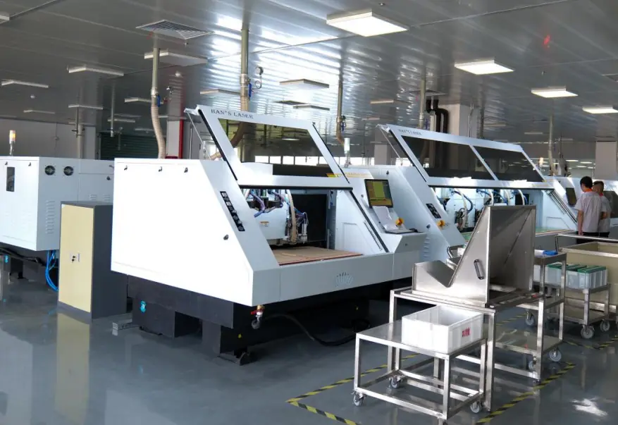
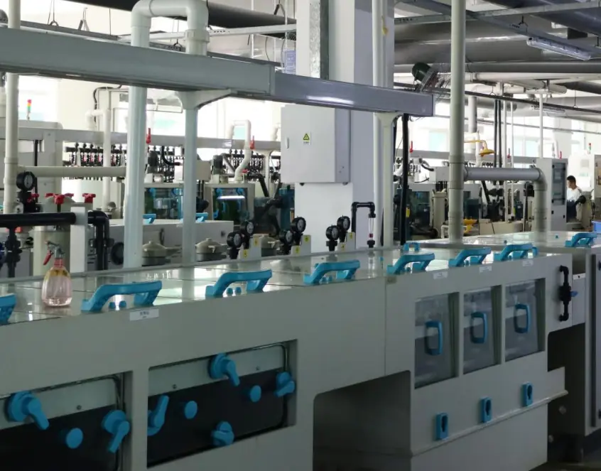
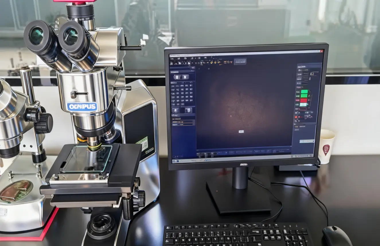
From prototype development to volume production, PCBMASTER supports your Rogers PCB projects with flexible manufacturing options and established quality control processes, helping you streamline sourcing and move your designs toward production with greater confidence.
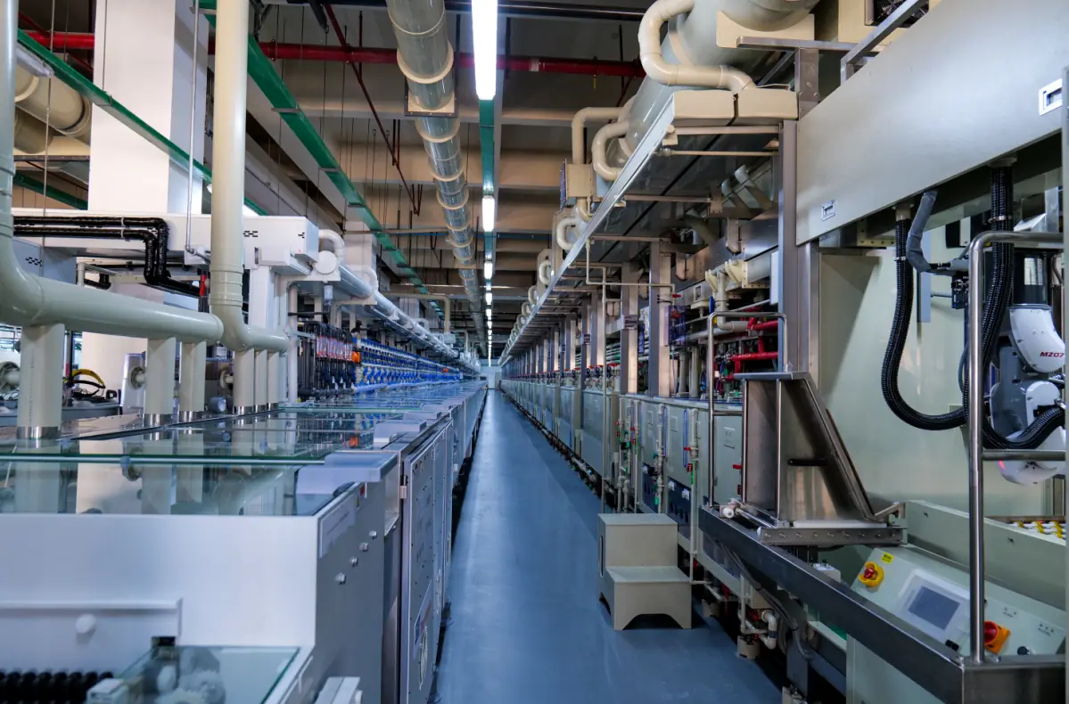
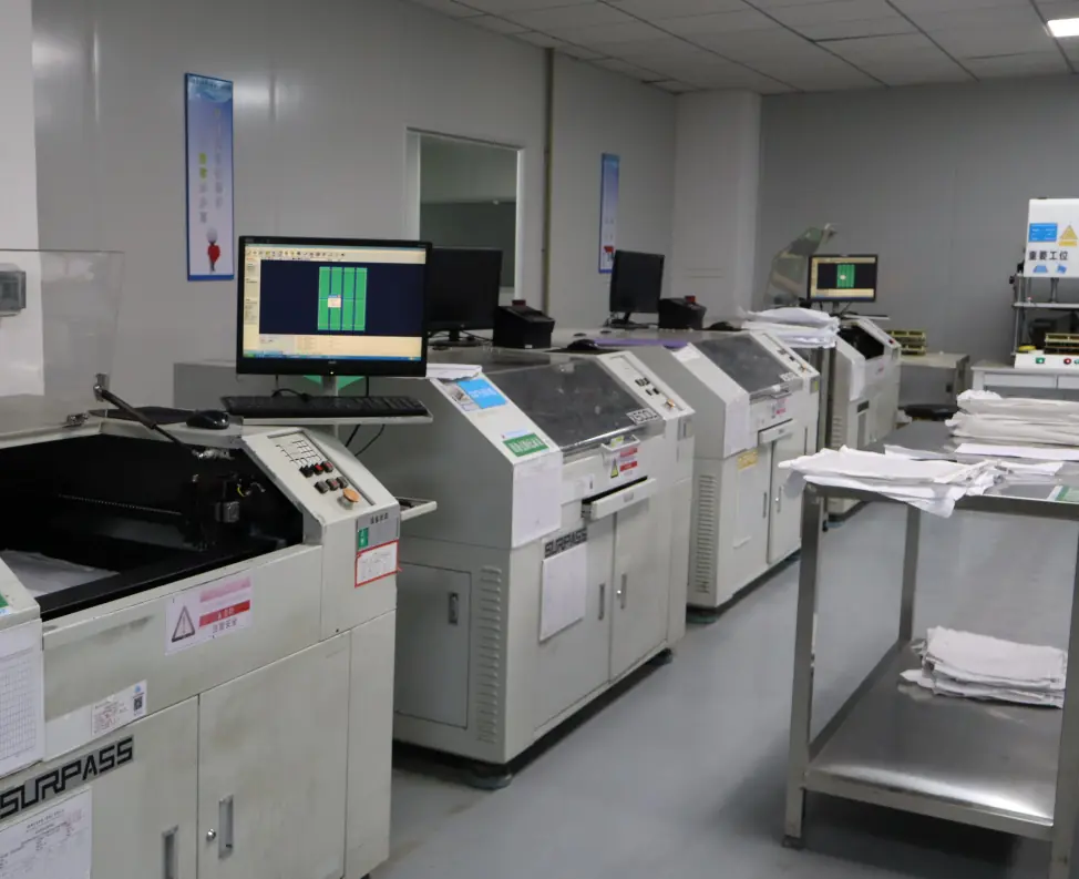
PCB manufacturing process 2
PCB manufacturing process 1
PCB manufacturing process 3
PCB manufacturing process 4
PCB manufacturing process 5
02 Rogers PCB Basics

What Is Rogers PCB

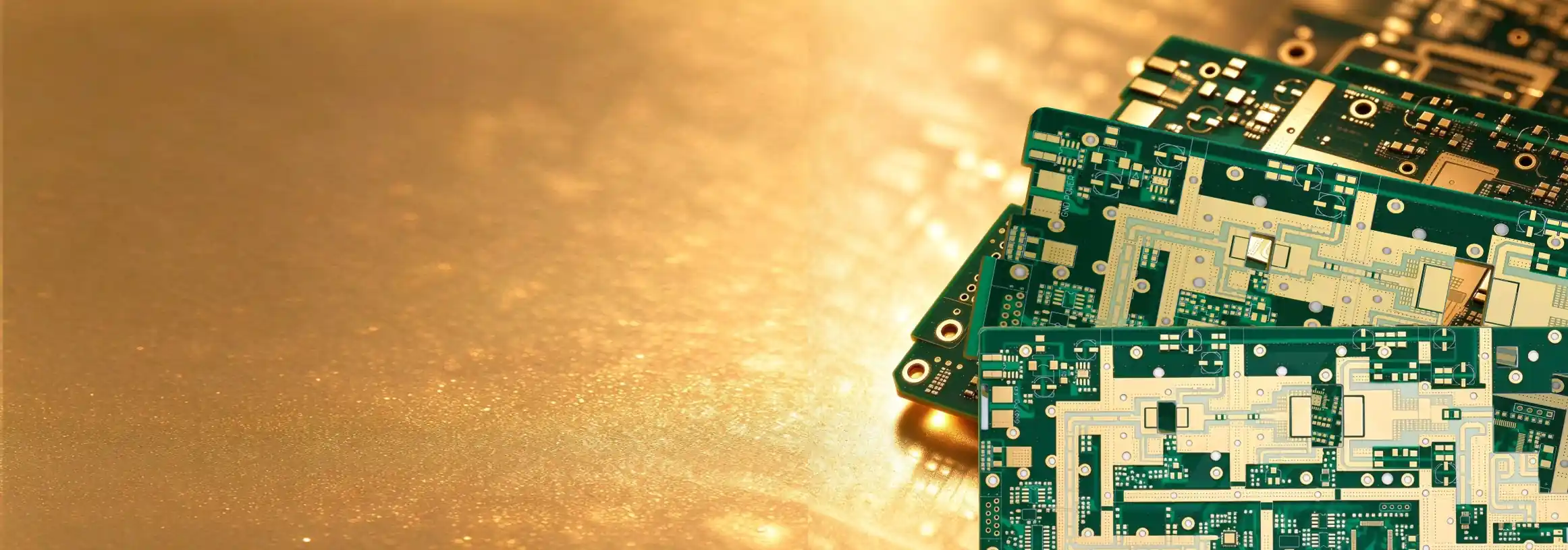
A Rogers PCB is a printed circuit board manufactured using high-frequency copper-clad laminates from Rogers Corporation. Compared with conventional FR-4 materials, selected Rogers laminates offer dielectric properties and low-loss characteristics suited to demanding RF and microwave applications. Different material series vary in dielectric constant (Dk), dissipation factor (Df), thermal performance, and processing requirements. Rogers PCBs are commonly used in antenna systems, radar equipment, wireless communications, and other high-frequency electronic devices. The final electrical performance depends on material selection, stack-up design, copper geometry, fabrication tolerances, and operating conditions.

PCBMASTER provides custom Rogers PCB manufacturing solutions tailored to your project requirements, including material selection support, single-sided, double-sided, and multilayer fabrication, Gerber file reviews, stack-up evaluation, controlled impedance manufacturing, and applicable quality inspections. From prototype development to volume production, our team helps you evaluate manufacturing feasibility and select suitable solutions for your RF and microwave designs.

03 Material Advantages

Rogers PCB Features

Rogers PCBs feature specialized electrical, thermal, and mechanical properties that make them suitable for demanding high-frequency applications, with specific characteristics varying by laminate type.

01

Low Dielectric Loss

Selected Rogers laminates, such as RO4003C and RO4350B, offer low dielectric loss to help reduce signal loss in high-frequency RF and microwave circuits.

02

Stable Dielectric Properties

RO4000 series laminates provide stable dielectric properties across a broad frequency range, helping you achieve more predictable circuit performance.

03

Low Moisture Absorption

RO4003C and RO4350B have low typical water absorption values of 0.04% and 0.05%, respectively, helping limit moisture-related changes in electrical performance.

04

High Thermal Conductivity

RO4360G2 offers a typical thermal conductivity of 0.75 W/m·K, helping transfer heat through the laminate more effectively than materials with lower thermal conductivity.

05

Low Z-Axis Thermal Expansion

RO4350B has a typical Z-axis coefficient of thermal expansion of 32 ppm/°C, helping improve plated through-hole reliability during thermal cycling.

06

Low Temperature Coefficient of Dielectric Constant

RO4000 series laminates feature a low temperature coefficient of dielectric constant, helping reduce temperature-related variation in electrical performance.

07

Multiple Dielectric Constant Options

Rogers offers laminates with different dielectric constant values, allowing you to select a material suited to your impedance, circuit size, and RF design requirements.

08

Compatibility with Standard PCB Processing

RO4003C and RO4350B can be fabricated using standard epoxy/glass PCB processes, helping simplify manufacturing without the specialized processing required by some PTFE-based materials.

04 材料

Rogers PCB Types and Material Options

Each Rogers PCB material offers different electrical and thermal characteristics. Understanding these differences helps you choose a laminate that meets your frequency, circuit size, and performance requirements.

Rogers Material Dk Overview
Rogers RO4003C PCB Dk ≈ 3.38 With a low dissipation factor and a dielectric constant of approximately 3.38, RO4003C helps you reduce dielectric losses while maintaining predictable high-frequency performance. It is suitable for cost-conscious RF and microwave designs.
Rogers RO4350B PCB Dk ≈ 3.48 RO4350B combines a dielectric constant of approximately 3.48 with low dielectric loss and low Z-axis thermal expansion. You can consider it for RF modules and multilayer circuits requiring stable electrical performance and reliable plated through-holes.
Rogers RO3003 PCB Dk ≈ 3.00 RO3003 features a dielectric constant of approximately 3.00 and low dielectric loss, with good dielectric stability over temperature. It is suitable for high-frequency designs where consistent electrical performance across temperature changes matters.
Rogers RO3010 PCB Dk ≈ 10.2 With a high dielectric constant of approximately 10.2, RO3010 helps you reduce circuit dimensions in suitable RF and microwave designs. It is worth evaluating when board space is limited and the electrical design supports a high-Dk material.
Rogers RT/duroid 5880 PCB Dk ≈ 2.20 RT/duroid 5880 offers a low dielectric constant of approximately 2.20 and an exceptionally low dissipation factor. It is well suited to microwave and millimeter-wave circuits where minimizing dielectric loss is a priority.
Rogers RT/duroid 5870 PCB Dk ≈ 2.33 RT/duroid 5870 combines a dielectric constant of approximately 2.33 with low dielectric loss. Consider it for RF and microwave circuits requiring low-loss signal transmission and consistent dielectric properties.
Rogers RO3006 PCB Dk ≈ 6.15 RO3006 features a dielectric constant of approximately 6.15 and low dielectric loss. Its higher Dk can help you achieve more compact circuit structures when the impedance and frequency requirements are properly accounted for.
Rogers Mixed-Laminate PCB Hybrid A Rogers mixed-laminate PCB combines high-frequency Rogers materials with other laminates, such as FR-4. This approach helps you reserve premium materials for critical RF layers while managing material cost and multilayer stack-up requirements.

Tailored to You

Your Rogers PCB, Built Around Your Design Requirements

From laminate selection to custom fabrication, PCBMASTER helps you evaluate material options, manufacturing constraints, and quality requirements for your high-frequency PCB projects.

Get a Rogers PCB Quote
05 アプリケーション

Rogers PCB Applications

Rogers PCBs are used in high-frequency circuits where dielectric loss, electrical consistency, and impedance control can affect system performance. Depending on your operating frequency and design requirements, the right Rogers laminate can help improve signal transmission, support precise RF performance, and meet application-specific needs.

RF Communication

Carry RF signals in transceivers, power amplifiers, and front-end circuits, where low-loss laminates help reduce signal attenuation at high frequencies.

Antenna Systems

Form antenna elements and feed networks, where controlled dielectric properties help achieve the required impedance, bandwidth, and antenna performance.

Radar Electronics

Support radar transmit-and-receive circuits, where low-loss materials and stable dielectric properties help preserve signal quality for accurate detection.

Satellite Communications

Connect RF and microwave circuit stages in satellite transceivers and ground terminals, where low dielectric loss helps limit signal attenuation.

Millimeter-Wave Electronics

Serve as substrates for millimeter-wave transmission lines and RF circuits, where precise dielectric properties and low insertion loss are important.

自動車電子機器

Support automotive radar antenna boards and selected RF modules, where stable high-frequency performance helps meet sensing and wireless connectivity requirements.

Test and Measurement

Provide substrates for RF test fixtures and microwave measurement circuits, where consistent dielectric properties help maintain predictable electrical results.

Wireless Infrastructure

Support base-station antennas, RF filters, and power amplifiers, where low-loss laminates help manage insertion loss in high-frequency signal paths.

06 ケーススタディ

Rogers PCB Manufacturing Case Studies

PCBMASTER has supported diverse Rogers PCB projects, solving complex engineering challenges with tailored material selection, precision fabrication, and reliable quality control to meet customers’ performance requirements.

Case 01

RO4350B PCB for an RF Power Amplifier Module

Challenge: A wireless equipment developer needed a compact RF power amplifier PCB operating at 3.5 GHz, with a 50 Ω RF interface and a board size of 60 × 45 mm. The main challenge was maintaining low signal loss and controlled impedance within a limited layout.

Solution: We selected RO4350B laminate with a nominal dielectric thickness of 0.508 mm and 35 μm copper foil. After reviewing the stack-up and RF trace geometry, we fabricated the PCB and performed dimensional inspections, electrical continuity and isolation tests, and impedance coupon measurements. Vector network analyzer testing confirmed that the prototype met the specified impedance tolerance of ±10% and the project’s insertion-loss requirements.

Result: The finished RO4350B PCB provided low-loss RF transmission paths and controlled 50 Ω impedance for the amplifier circuit. It integrated the components within the required footprint and served as the electrical platform for RF module validation.

Case 02

RT/duroid 5880 PCB for a High-Frequency Antenna

Challenge: A communications equipment developer required a low-loss antenna PCB for a 24 GHz prototype. The 80 × 50 mm board incorporated a microstrip feed network connected to an antenna array, making trace geometry and dielectric consistency critical to impedance matching.

Solution: We used RT/duroid 5880 with a nominal dielectric thickness of 0.254 mm and 18 μm copper foil. Our manufacturing process accounted for the material’s PTFE-based construction and controlled the feed-line geometry and etching tolerances. After fabrication, we checked board dimensions, electrical continuity, and feed-line impedance, then evaluated antenna performance using RF measurement equipment.

Result: The completed RT/duroid 5880 PCB provided a low-loss substrate for the antenna array and feed network. It met the specified return-loss and operating-band requirements and was used in the customer’s system-level prototype evaluation.

Case 03

Rogers and FR-4 Hybrid Multilayer PCB for a Wireless Transceiver

Challenge: An industrial wireless equipment manufacturer needed a six-layer PCB integrating RF circuits, digital control, and power management. An all-Rogers construction would increase material costs, while an all-FR-4 design would not meet the RF section’s loss requirements.

Solution: We developed a hybrid stack-up using RO4350B for the RF layers and FR-4 for selected control and digital layers. The engineering review covered dielectric thicknesses, copper distribution, bonding materials, lamination compatibility, and impedance requirements. After fabrication, we performed layer-registration inspections, plated through-hole checks, electrical testing, and impedance measurements.

Result: The finished hybrid PCB integrated the RF and control circuits in a single six-layer board. By reserving RO4350B for the high-frequency sections, the design met the specified impedance and electrical acceptance criteria without using specialty laminate throughout the entire stack-up.

Case 04

Controlled-Impedance Rogers PCB for a 77 GHz Radar Module

Challenge: An automotive electronics supplier required a four-layer PCB for a 77 GHz radar front-end module. The design connected RF circuitry and antenna-feed lines with low-frequency control electronics. Precise trace geometry, reference-plane continuity, and connector transitions were critical to the high-frequency signal path.

Solution: We selected a suitable low-loss Rogers laminate and reviewed the stack-up, impedance targets, ground-via placement, and RF transitions before fabrication. Quality checks included dimensional inspection, electrical continuity and isolation tests, impedance coupon measurements, and RF evaluation using calibrated high-frequency equipment.

Result: The finished Rogers PCB provided controlled-impedance transmission paths between the radar front-end and antenna-feed network. It passed the project’s specified manufacturing and RF acceptance tests and was integrated into the radar module for system-level evaluation.

07 Customer Feedback

What Customers Say About PCBMASTER's Rogers PCB

With proven expertise in Rogers PCB manufacturing, PCBMASTER helps customers overcome high-frequency design challenges through engineering support, precision fabrication, consistent quality, and dependable delivery.

“
Choosing a Rogers laminate isn’t just about picking a Dk value. We also had to consider stack-up thickness, impedance, and fabrication tolerances. PCBMASTER reviewed our design and pointed out a few details worth checking before production. I appreciated that the team discussed the engineering trade-offs instead of simply accepting the files and moving on.
Michael Weber Michael WeberRF Design Engineer · Wireless Communications · Germany
“
For us, a board that passes one test is not enough. We need consistent results across the order and inspection records that support our incoming quality checks. Our Rogers PCB requirements are quite specific, so dimensional accuracy, electrical testing, and clear quality documentation are all important when evaluating a manufacturing supplier.
Sarah Mitchell サラ・ミッチェルQuality Assurance Manager · RF Electronics · United States
“
A competitive quote is useful, but it doesn’t mean much if the boards arrive after our testing window. With custom Rogers PCB orders, we need realistic lead times and coordination when project priorities change. I look for a supplier that understands the schedule pressure and keeps delivery planning aligned with the wider project.
Daniel Foster Daniel FosterProcurement Manager · Automotive Electronics · United Kingdom
“
Honestly, clear answers save us a lot of time. When a Rogers PCB detail needs clarification or a design change comes up, I want to know what needs to be confirmed, whether it affects manufacturability, and how it impacts the order. Direct technical communication and timely status updates make collaboration much easier.
Emily Chen Emily ChenHardware Development Engineer · Telecommunications · Canada

よくある質問 Rogers PCB

その他の質問がありますか?弊社の技術チームが支援の準備ができています。

テクニカルサポートに連絡

Ready to Manufacture Your Rogers PCB?

Send us your Gerber files, material requirements, stack-up details, and quantity. Our team can review your specifications and help evaluate a suitable manufacturing solution for your RF or microwave PCB project.

ホーム Quote 私の注文
Get Coupon