








Power Supply Capacitors: Types, Selection, Placement, and PCB Design Considerations
Power supply capacitors are essential components in PCB power circuits, where they help smooth rectified voltage, stabilize DC rails, suppress noise, and provide transient current. The right capacitor depends on capacitance, voltage rating, ESR , ripple-current capability, frequency characteristics, temperature, lifetime, and physical size. For PCB designers, capacitor selection must also be considered together with placement, trace impedance, thermal conditions, and the overall power-supply topology.
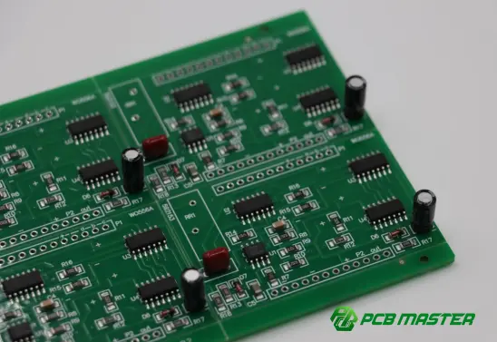
What Are Power Supply Capacitors?
Power supply capacitors are capacitors used in power conversion and distribution circuits to store electrical energy, filter voltage fluctuations, reduce ripple, and maintain power-rail stability .
They are commonly found on PCBs used in:
- AC-DC power supplies
- DC-DC converters
- LDO regulators
- Battery management systems
- Industrial control equipment
- Automotive electronics
- Communications equipment
- Consumer electronics
- Servers and computing hardware
A typical power supply may use several capacitors rather than relying on a single component. Different capacitor technologies perform different functions across the frequency spectrum.
The key point is that a power supply capacitor is not selected based on capacitance alone. Voltage rating, ESR, ripple current, temperature rating, lifetime, package size, and PCB placement can all affect circuit performance and reliability.
What Types of Capacitors Are Used in Power Supplies?
Several capacitor technologies are commonly used in power-supply circuits.
| Capacitor Type | Typical Role | Major Characteristics | Common PCB Application |
|---|---|---|---|
| Aluminum Electrolytic | Bulk filtering | High capacitance, relatively high ripple-current capability | DC bus, output filtering |
| Ceramic MLCC | High-frequency bypassing | Low ESR/ESL, excellent high-frequency performance | IC power rails, DC-DC converters |
| Tantalum | Filtering and decoupling | Stable capacitance, compact size | Power rails and compact electronics |
| Polymer Capacitor | Output filtering | Low ESR and good ripple performance | DC-DC converters, processors |
| Film Capacitor | DC-link/filtering | Low loss, good stability and high reliability | Power electronics, inverter circuits |
The correct combination depends on the topology and operating conditions.
For example, an aluminum electrolytic capacitor may provide the bulk energy storage , while an MLCC placed close to a switching device handles higher-frequency transient currents .
Aluminum Electrolytic Capacitors
Aluminum electrolytic capacitors are widely used when a relatively large capacitance is required.
They are particularly useful for:
- DC-link filtering
- Rectified AC smoothing
- Bulk energy storage
- Low-frequency ripple reduction
However, their electrical characteristics vary significantly with temperature, frequency, voltage, and lifetime.
For applications requiring long operating life or elevated temperatures, designers should pay particular attention to the capacitor's rated lifetime and ripple-current specification .
Ceramic Capacitors
Multilayer ceramic capacitors (MLCCs) are particularly valuable for high-frequency power filtering.
Their advantages include:
- Low ESR
- Low ESL
- Small package size
- High-frequency response
- Fast transient response
They are commonly placed close to power ICs, MOSFETs, switching regulators, and other high-speed switching elements.
However, designers must account for DC-bias capacitance reduction , especially when using high-capacitance Class 2 ceramic capacitors.
Film Capacitors
Film capacitors are frequently used in power electronics where stability, low loss, and high reliability are important.
Applications can include:
- DC-link circuits
- Inverters
- Motor drives
- Power-factor correction
- High-voltage filtering
Their relatively larger physical size can be a limitation compared with MLCCs and other compact capacitor technologies.
How Do Power Supply Capacitors Work on a PCB?
A power supply capacitor can perform several different functions depending on where it is located within the circuit.
1. Bulk Energy Storage
Large capacitors can store energy and provide current when the supply voltage temporarily falls.
This helps reduce the amplitude of low-frequency voltage fluctuations.
2. Voltage Ripple Reduction
After rectification or switching conversion, the output voltage may contain unwanted ripple.
The capacitor absorbs and releases charge to help smooth the voltage waveform.
3. High-Frequency Noise Suppression
Small ceramic capacitors can provide a low-impedance path for high-frequency noise.
This is particularly important around switching regulators and digital IC power rails.
4. Transient Current Support
When a load suddenly demands additional current, a nearby capacitor can temporarily supply part of that current before the power supply control loop responds.
This is why capacitor placement can be just as important as capacitance value .
How Should You Select a Power Supply Capacitor?
A practical selection process should consider at least the following parameters.
Capacitance
The required capacitance depends on the circuit topology, switching frequency, load profile, allowable ripple, and transient requirements.
A larger capacitance is not automatically better .
Excessive capacitance can affect:
- Startup behavior
- Inrush current
- Control-loop stability
- Physical PCB size
- Cost
- Component reliability
The target should be the capacitance required by the circuit rather than simply choosing the largest available value.
Voltage Rating
The capacitor's rated voltage should provide sufficient margin above the maximum voltage it will experience.
Designers should consider:
- Nominal voltage
- Maximum operating voltage
- Transient voltage
- Ripple voltage
- Temperature effects
For high-voltage power supplies, voltage derating becomes particularly important.
ESR
Equivalent Series Resistance (ESR) directly affects power loss and ripple behavior.
A simplified relationship is:
P = Iᵣₘₛ² × ESR
where Iᵣₘₛ is the capacitor's RMS ripple current.
Lower ESR can reduce resistive losses, but extremely low ESR can also change the behavior of some regulator control loops. Therefore, the capacitor should meet the regulator's specified stability requirements rather than simply having the lowest possible ESR.
Ripple Current
The capacitor must withstand the expected RMS ripple current without excessive heating.
If ripple current is too high, internal losses increase and capacitor temperature rises.
For electrolytic capacitors in particular, ripple-current capability can have a significant influence on service life.
Temperature Rating
Temperature should be evaluated based on the actual thermal environment of the PCB , not merely the ambient room temperature.
Capacitors located near:
- MOSFETs
- Transformers
- Inductors
- Power resistors
- Heat sinks
may experience substantially higher temperatures than the surrounding air.
Lifetime
For applications such as industrial equipment, automotive electronics, telecom equipment, and servers, capacitor lifetime can become a critical reliability factor.
The designer should consider both the capacitor's specified lifetime and the actual operating temperature.
Why Does Capacitor Placement Matter on a PCB?
One of the most common PCB power-design mistakes is treating a capacitor as an ideal component.
At high frequencies, the capacitor's ESR and ESL become important. PCB traces and vias also introduce parasitic inductance and resistance.
Therefore, even an excellent capacitor can perform poorly if it is placed too far from the device it is intended to support.
For switching regulators, the high-frequency current loop should generally be kept short and compact .
For example, the input bypass capacitor should be positioned close to the regulator's relevant input and return paths.
Practical PCB Placement Principles
- Place high-frequency bypass capacitors close to the power pins.
- Minimize the high-current loop area.
- Keep power and return paths short.
- Avoid unnecessary vias in high-frequency current paths.
- Use appropriate copper width for high-current connections.
- Consider thermal spacing around high-power components.
- Follow the regulator IC manufacturer's recommended layout whenever available.
Common Mistakes When Designing Power Supply Capacitor Networks
Mistake 1: Selecting Capacitors Only by Capacitance
Two 100 µF capacitors can have very different ESR, ripple-current ratings, temperature characteristics, and lifetime.
Capacitance alone does not define capacitor performance.
Mistake 2: Ignoring DC-Bias Effects of MLCCs
The effective capacitance of some ceramic capacitors can decrease substantially under applied DC voltage.
Therefore, designers should evaluate the effective capacitance at the actual operating voltage , rather than relying only on the nominal value printed in the component specification.
Mistake 3: Placing the Capacitor Too Far Away
Long PCB traces introduce parasitic inductance.
At high frequencies, this can significantly reduce the capacitor's effectiveness.
Mistake 4: Ignoring Ripple Current
A capacitor may meet the capacitance and voltage requirements but still fail thermally if its ripple-current capability is inadequate.
Mistake 5: Using Excessive Capacitance Without Checking the Power Supply
Increasing capacitance can increase startup and inrush current and may affect the control loop.
The complete power supply should therefore be evaluated rather than optimizing one component in isolation.
Power Supply Capacitors and PCB Manufacturing
Capacitor selection is closely connected with PCB manufacturing and assembly.
The designer needs to consider:
- Component package
- Pad dimensions
- Component spacing
- Copper thickness
- Thermal relief
- Soldering process
- Component height
- Creepage and clearance
- High-current routing
- Thermal management
- Assembly tolerances
For high-density PCB designs, these requirements become more challenging because power components and passive components compete for limited board space.
For advanced power electronics, the PCB stack-up, copper thickness, dielectric material, via structure, and thermal design can all influence power-distribution performance.
How PCB Engineering Support Can Reduce Power-Supply Design Risks
A robust PCB manufacturing process should begin before fabrication.
Engineering review can identify potential issues such as:
- Insufficient clearance around high-voltage capacitors
- Incorrect footprint dimensions
- Inadequate copper capacity
- Poor capacitor placement
- Manufacturability problems
- Thermal bottlenecks
- Component availability concerns
- Potential assembly conflicts
For example, PCBMASTER provides free engineering file checking before production, allowing PCB designs to be reviewed for manufacturability, performance considerations, and cost efficiency.
For projects involving complex power electronics, this type of DFM review can be valuable because capacitor selection and PCB layout cannot be completely separated from manufacturing constraints.
PCBMASTER's Approach to Power-Supply PCB Projects
As a PCB and PCBA manufacturer serving electronics applications across multiple industries, PCBMASTER supports projects ranging from quick-turn PCB prototypes to advanced multilayer , HDI , high-frequency , rigid-flex , FPC , and metal-core PCBs .
Its manufacturing capabilities include 24-hour rapid prototyping , advanced AOI inspection, multiple quality inspections, and engineering support throughout the production process. PCBMASTER also operates an 80,000 m² factory and provides PCB manufacturing, PCBA assembly, component sourcing, and related engineering services.
For power-supply applications, the practical value is not simply manufacturing the board. The objective is to ensure that the electrical design, component selection, PCB layout, manufacturability, assembly, and quality control work together as one system .
A Practical Checklist for Power Supply Capacitors
Before releasing a power-supply PCB to production, verify:
| Checkpoint | Key Question |
|---|---|
| Capacitance | Does the effective capacitance meet the circuit requirement? |
| Voltage rating | Is sufficient voltage margin available? |
| ESR | Is ESR compatible with the power-supply topology and control loop? |
| Ripple current | Can the capacitor safely handle the expected RMS ripple current? |
| Temperature | What temperature will the capacitor actually experience? |
| Lifetime | Does the expected service life meet the application requirement? |
| Placement | Is the capacitor sufficiently close to the relevant power/current loop? |
| PCB layout | Are high-current and high-frequency loops minimized? |
| Clearance | Are creepage and clearance requirements satisfied? |
| Footprint | Does the PCB footprint match the actual component? |
| Assembly | Is the component compatible with the intended SMT/THT process? |
| DFM | Has the complete PCB design been reviewed before fabrication? |
Conclusion: Power Supply Capacitors Are a System-Level Design Decision
Power supply capacitors are fundamental to reliable PCB power systems, but selecting them is more than choosing a capacitance value.
A reliable design considers capacitance, voltage rating, ESR, ripple current, temperature, lifetime, capacitor technology, PCB placement, parasitic effects, and manufacturing constraints together .
For engineers developing power supplies, DC-DC converters, industrial controllers, automotive electronics, or other power-sensitive products, the most effective approach is to evaluate the capacitor as part of the complete power-delivery network , rather than as an isolated component.
From prototype fabrication and engineering file review to PCBA assembly and volume production, a capable PCB manufacturing partner can also help identify manufacturability and reliability risks before they become production problems.
The best power-supply capacitor is not necessarily the largest, cheapest, or lowest-ESR component—it is the one whose electrical, thermal, mechanical, and manufacturing characteristics match the complete PCB design.
Tags: #PowerSupplyCapacitors #PCBDesign #PowerSupplyDesign #PCB #PCBA #SMT #ElectronicsEngineering #PowerElectronics #DCConverter #PCBManufacturing #PCBMASTER #EngineeringInsights
About the Author

Carol Luo
PCB Design EngineerI'm Carol, a PCB Engineer at PCBMASTER with experience in PCB design and manufacturing engineering since 2018. I focus on translating engineering requirements into reliable PCB solutions, with expertise in stack-up design, material selection, and design-for-manufacturing (DFM). I share practical engineering insights from real-world PCB design and production experience.
Visit Carol Luo's Profile

