








Multilayer Ceramic Capacitor (MLCC): Structure, Types, Applications, and PCB Design Considerations
A multilayer ceramic capacitor (MLCC) is a compact, non-polarized capacitor constructed from alternating ceramic dielectric and metal electrode layers. Its high capacitance-to-volume ratio, low ESR/ESL, reliability, and suitability for automated SMT assembly make it one of the most widely used passive components in modern electronics. Understanding MLCC construction, dielectric classes, capacitance characteristics, DC bias, voltage ratings, and PCB layout is essential for reliable circuit design and manufacturing.
What Is a Multilayer Ceramic Capacitor?
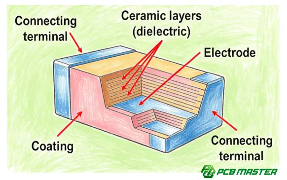
A multilayer ceramic capacitor , commonly abbreviated as MLCC , is a surface-mount capacitor manufactured by stacking multiple layers of ceramic dielectric material and internal metal electrodes.
Unlike a conventional single-layer ceramic capacitor, an MLCC contains many dielectric layers connected alternately to two external terminals. This multilayer construction significantly increases the effective electrode area while keeping the component physically small.
MLCCs are widely used for:
- Power supply decoupling
- High-frequency noise suppression
- Signal filtering
- DC blocking
- Voltage stabilization
- Resonant circuits
- Timing and control circuits
- Automotive electronics
- Industrial control systems
- Communication equipment
- Consumer electronics
- Computing and networking hardware
For PCB designers, MLCCs are particularly important because their electrical performance is strongly influenced not only by the capacitor specification but also by component placement, PCB layout, mounting, and assembly conditions .
How Does an MLCC Work?
An MLCC stores electrical energy in the electric field created between its electrodes.
Its ideal capacitance can be described as:
C = εA/d
Where:
- C = capacitance
- ε = dielectric permittivity
- A = effective electrode area
- d = dielectric thickness
The multilayer structure allows manufacturers to increase the effective electrode area without proportionally increasing component size.
As the number of dielectric and electrode layers increases, the capacitance can increase while maintaining a relatively small package footprint.
How Is a Multilayer Ceramic Capacitor Constructed?
The basic MLCC manufacturing process involves several key stages.
1. Ceramic Dielectric Preparation
A ceramic material is prepared according to the required electrical characteristics. Different dielectric formulations provide different combinations of capacitance stability, temperature performance, voltage capability, and losses.
2. Internal Electrode Formation
Metal electrode layers are deposited onto ceramic dielectric sheets. These electrode layers are designed to connect alternately to opposite external terminals.
3. Layer Stacking
Multiple ceramic dielectric and electrode layers are precisely stacked to form the multilayer structure.
The number and thickness of these layers are major factors determining the resulting capacitance and component dimensions.
4. Lamination and Cutting
The stacked structure is laminated and divided into individual capacitor bodies.
5. Sintering
The ceramic body undergoes controlled high-temperature sintering to form a mechanically stable structure and establish the required electrical properties.
6. External Termination
External terminals are formed so that alternating internal electrodes connect to opposite ends of the component.
7. Testing and Inspection
Electrical and mechanical characteristics are verified before the components are released for use.
What Are the Main Types of MLCCs?
MLCCs can be classified according to dielectric characteristics, capacitance stability, temperature behavior, and application requirements.
A particularly important distinction is between Class 1 and Class 2 ceramic dielectrics .
| Characteristic | Class 1 | Class 2 |
|---|---|---|
| Typical dielectric | C0G/NP0 | X7R, X5R, etc. |
| Capacitance stability | Very high | Lower |
| Temperature dependence | Very low | Higher |
| Voltage dependence | Very low | Significant for some materials |
| Capacitance density | Lower | Higher |
| Typical applications | Precision, RF, timing | Decoupling, filtering, power circuits |
C0G/NP0 MLCC
C0G/NP0 capacitors offer excellent capacitance stability over temperature and voltage.
They are commonly selected for applications where predictable electrical behavior is more important than achieving extremely high capacitance density.
Typical applications include:
- RF circuits
- Oscillators
- Precision filters
- Timing circuits
- Analog circuits
X7R MLCC
X7R is a Class 2 ceramic dielectric commonly used when relatively high capacitance is required in a compact package.
It is widely used for:
- Power supply decoupling
- IC bypassing
- Filtering
- Automotive electronics
- Industrial electronics
The capacitance is less stable than C0G/NP0 and can change with temperature and applied DC voltage.
X5R MLCC
X5R is another widely used Class 2 dielectric.
It provides high capacitance density and is frequently found in compact electronic products where PCB area is limited.
However, designers must consider DC bias effects , particularly when using high-capacitance X5R components at relatively high operating voltages.
What Do MLCC Markings Such as C0G, X7R, and X5R Mean?
The dielectric code provides information about temperature characteristics.
For example, X7R indicates a defined operating temperature range and a specified maximum capacitance change across that range.
Similarly, X5R provides a different temperature range.
These codes should not be interpreted simply as quality rankings. The appropriate dielectric depends on the electrical requirements of the circuit.
Why Is MLCC Capacitance Not Always the Rated Capacitance?
One of the most important practical issues with MLCCs is that the nominal capacitance printed in a bill of materials does not necessarily represent the capacitance under actual operating conditions.
For Class 2 ceramic capacitors, capacitance can change because of:
- DC bias
- Temperature
- Aging
- AC voltage
- Mechanical stress
- Frequency
DC Bias Effect
The DC bias effect is particularly important.
For example, a high-capacitance ceramic capacitor may have its nominal capacitance specified under relatively low measurement voltage. When a significant DC voltage is applied during actual operation, the effective capacitance can decrease substantially.
Therefore, simply selecting a capacitor based on its nominal value—such as 10 µF —may not be sufficient.
Designers should examine the manufacturer's capacitance-versus-DC-bias curve under the actual operating voltage.
MLCC Package Size and Electrical Performance
MLCCs are available in many surface-mount package sizes.
Common examples include:
| Package | General characteristic | Typical consideration |
|---|---|---|
| 0201 | Extremely compact | High-density designs |
| 0402 | Small footprint | General compact electronics |
| 0603 | Widely used | Good balance of size and assembly |
| 0805 | Larger footprint | Higher capacitance or easier assembly |
| 1206 | Larger body | Higher capacitance/voltage or mechanical considerations |
The actual package designation and dimensions can vary depending on the manufacturer's standard.
Smaller packages can help reduce PCB area and parasitic effects, but they can also introduce manufacturing and handling challenges.
For high-speed or high-frequency circuits, smaller package sizes can be advantageous because reduced physical dimensions can contribute to lower parasitic inductance.
Why Are MLCCs So Important in PCB Design?
An MLCC is not simply a passive component placed anywhere on a PCB.
Its effectiveness in applications such as IC decoupling depends heavily on the current path between the capacitor, power plane, and device pins.
For high-frequency decoupling, designers generally want:
IC power pin → MLCC → ground → return path
to have extremely low impedance.
This means the following PCB design factors matter:
- Distance between MLCC and IC power pins
- Via placement
- Trace length
- Trace width
- Power and ground plane configuration
- Package size
- Parasitic inductance
- Current-loop area
MLCC Placement for Decoupling
A common mistake is selecting an appropriate capacitor but placing it too far from the device it is intended to decouple.
At high frequencies, PCB interconnect inductance can become significant. Consequently, increasing the distance between the capacitor and IC can reduce the effectiveness of the decoupling network.
Practical principle: For high-frequency decoupling, prioritize a short, low-inductance current path rather than simply minimizing the distance in a geometric sense.
What Are the Main Applications of MLCCs?
Power Supply Decoupling
MLCCs are extensively used near integrated circuits to provide local charge storage and reduce high-frequency power supply noise.
Filtering
MLCCs can form RC, LC, and other filtering networks for suppressing unwanted frequency components.
RF and High-Frequency Circuits
Low-loss ceramic capacitors such as C0G/NP0 are useful in RF circuits where capacitance stability and predictable high-frequency behavior are important.
Automotive Electronics
MLCCs are used throughout automotive electronic systems, including:
- ECU circuits
- ADAS electronics
- Infotainment
- Power management
- Battery management systems
- Vehicle communication systems
Automotive applications may require stricter reliability, temperature, voltage, and mechanical requirements.
Industrial Control
Industrial control equipment often uses MLCCs for power filtering, signal conditioning, noise suppression, and local decoupling.
Common MLCC Design Mistakes
Mistake 1: Selecting Only by Nominal Capacitance
A 10 µF capacitor is not necessarily operating as an effective 10 µF capacitor under the application's actual DC voltage.
Better approach: Check effective capacitance under operating bias.
Mistake 2: Ignoring Voltage Derating
Operating an MLCC too close to its rated voltage can reduce design margin.
Better approach: Consider operating voltage, transient conditions, temperature, aging, and application-specific derating requirements.
Mistake 3: Placing Decoupling Capacitors Too Far From the IC
A theoretically correct capacitor can become less effective when PCB parasitics dominate the high-frequency current path.
Better approach: Place critical decoupling capacitors close to the relevant power pins and optimize the return path.
Mistake 4: Ignoring Mechanical Stress
MLCC ceramic bodies are relatively brittle. PCB bending, board depanelization, connector insertion forces, or other mechanical stresses can contribute to cracking.
This is particularly important for larger MLCC packages and applications exposed to significant mechanical or thermal stress.
Mistake 5: Treating All Ceramic Capacitors as Electrically Equivalent
C0G/NP0, X7R, and X5R can have substantially different electrical characteristics.
Better approach: Select the dielectric according to the actual circuit requirement rather than capacitance alone.
MLCC Selection Checklist
When selecting a multilayer ceramic capacitor for a PCB design, evaluate at least the following parameters:
| Selection Parameter | What to Check |
|---|---|
| Capacitance | Required nominal and effective capacitance |
| Rated voltage | Normal operating voltage and transients |
| Dielectric | C0G/NP0, X7R, X5R, etc. |
| DC bias | Capacitance loss at operating voltage |
| Temperature | Operating temperature range |
| Package size | PCB space and assembly requirements |
| ESR/ESL | Frequency-dependent performance |
| Tolerance | Required capacitance tolerance |
| Aging | Long-term capacitance stability |
| Mechanical reliability | PCB stress and application environment |
| Assembly compatibility | SMT process and PCB land pattern |
How Does PCB Manufacturing Affect MLCC Reliability?
The capacitor itself is only one part of the reliability equation. PCB fabrication and SMT assembly processes also influence MLCC performance.
A reliable manufacturing process should control factors such as:
- PCB dimensional accuracy
- Pad geometry
- Surface finish
- Solder paste deposition
- Component placement accuracy
- Reflow profile
- Board handling
- Inspection
- Post-assembly testing
For complex PCB assemblies, DFM review before production can identify potential pad, spacing, component-placement, and assembly issues before they become manufacturing problems.
This is one reason engineering review should occur before PCB fabrication rather than after assembly problems appear .
PCBMASTER's Approach to PCB and PCBA Manufacturing
For projects incorporating large numbers of MLCCs, the component itself must be considered together with the PCB, SMT process, and final PCBA requirements.
PCBMASTER provides PCB, PCBA, and SMT manufacturing with an engineering workflow that includes free engineering file review , helping identify manufacturability and performance-related issues before production.
Its manufacturing capabilities cover standard and advanced PCB technologies, including HDI , FPC , rigid-flex , high-frequency PCB , and metal-core PCB , allowing MLCC-based circuits to be manufactured across a broad range of electronic applications.
PCBMASTER also operates an 80,000 m² factory and supports PCB and PCBA production from prototyping through larger-scale manufacturing. Its quality system includes ISO 9001, IATF 16949, UL, and RoHS certifications.
For projects where component placement, PCB layout, SMT assembly, and reliability must work together, this integrated manufacturing approach can reduce the gap between the electrical design and the final assembled product.
Final Takeaway: What Should Engineers Remember About MLCCs?
A multilayer ceramic capacitor is a small component with surprisingly complex real-world behavior .
The most important design considerations are:
- Choose the dielectric according to the application.
- Do not assume nominal capacitance equals effective capacitance.
- Evaluate DC bias, temperature, aging, and frequency effects.
- Consider voltage margin and application-specific derating.
- Optimize MLCC placement and current-loop inductance for high-frequency decoupling.
- Account for mechanical stress and PCB assembly conditions.
- Review PCB layout and SMT manufacturability before production.
As electronic products continue to become smaller, faster, and more power-dense, MLCC selection is increasingly connected to PCB layout, signal integrity, power integrity, thermal design, and SMT manufacturing quality . Treating the capacitor, PCB, and assembly process as one integrated system is therefore more reliable than selecting passive components in isolation.
Tags: #MultilayerCeramicCapacitor #MLCC #CeramicCapacitor #PCBDesign #PCBA #SMT #PCBManufacturing #DecouplingCapacitor #PowerIntegrity #ElectronicsDesign #PCBMASTER #ElectronicsEngineering
About the Author

Carol Luo
PCB Design EngineerI'm Carol, a PCB Engineer at PCBMASTER with experience in PCB design and manufacturing engineering since 2018. I focus on translating engineering requirements into reliable PCB solutions, with expertise in stack-up design, material selection, and design-for-manufacturing (DFM). I share practical engineering insights from real-world PCB design and production experience.
Visit Carol Luo's Profile

