








LDO Power Module: Complete Guide to Working Principles, Design, and Applications
Power stability is an important requirement for modern electronic devices, particularly those that use sensitive analogue, RF and precision digital circuits. Even small voltage fluctuations can have an impact on the signal quality, system accuracy and overall reliability. So selecting the right power regulation solution is as important as choosing the core components on a PCB.
The LDO power module among the options is the best in terms of low noise output, easy implementation and reliable voltage regulation. But to achieve the best performance, it’s not simply a matter of adding a module to a design. To design stable and efficient electronic systems, you need to know how it works, its strengths and limitations, and follow proper PCB design practices.
The guide addresses LDO power modules’ working principles, key benefits, selection criteria, PCB design tips and typical use cases to help you make the right design decisions.
What Is an LDO Power Module?
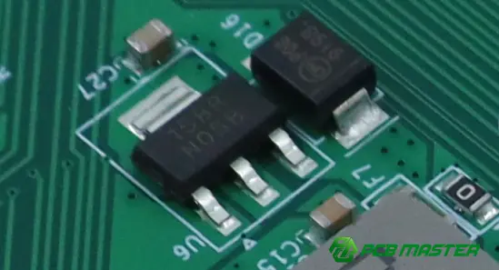
An LDO(Low Dropout Regulator) power module is a compact power supply that contains an LDO regulator and its supporting circuitry to provide a stable, low noise output voltage for reliable operation.
Definition and Core Components
An LDO power module is an LDO voltage regulator with most of the external components in one package or a ready-to-use circuit. The module has a simplified power stage design without losing voltage regulation. The engineer does not have to design the power stage from scratch.
A typical LDO power module includes:
- LDO regulator IC– Controls the output voltage.
- Input capacitor– Filters voltage fluctuations from the power source.
- Output capacitor– Improves output stability and transient response.
- Protection circuits– May include overcurrent, thermal shutdown, and short-circuit protection.
- PCB and thermal design– Helps dissipate heat and ensures reliable operation.
For example, if a microcontroller needs a clean, regulated 3.3V supply out of a 5V input, an LDO power module makes this easy to do with minimal design effort.
How It Differs from a Standard LDO Regulator
An LDO regulator is typically just one IC . An LDO power module is a more complete solution that includes the regulator and support components .
The difference is integration. Most stand-alone LDO regulators require the engineer to choose external capacitors, carefully design the PCB layout and check the circuit stability; Many of these can be combined into one solution with an LDO power module, making this work easier.
| Standard LDO Regulator | LDO Power Module |
|---|---|
| Single regulator IC | Integrated power solution |
| Requires external components | Includes key supporting components |
| More design flexibility | Faster implementation |
| Greater PCB design effort | Simplified PCB design |
An experienced hardware engineer can design a custom circuit with a discrete LDO regulator. If the product has a tight schedule, the development team may choose an LDO power module in order to save design time and avoid the risk of layout or stability problems.
Why It Is Used in Electronic Designs
An LDO power module is easy to build, provides a clean and constant power source and is perfect for sensitive electronic circuits.
Many electronic devices have parts that are not tolerant of noisy or unstable power. Analogue sensors, RF modules, audio circuits and precision measurement systems all need a stable voltage to work properly. The LDO power module is used to reduce the noise of the constant output voltage power supply.
And one more good thing about it is that it is simple in design. This means shorter development times, less parts and better overall design reliability for engineers. Much of the supporting circuitry is already integrated.
For example, a switching regulator might be used to efficiently step down the battery voltage on an IoT sensor board, and then an LDO power module could be used to supply clean power to the wireless communication chip. The combination results in better power efficiency and signal quality.
How Does an LDO Power Module Work?
A LDO power module takes a higher voltage input and drops it to a constant (lower) voltage output. It has a control circuit that monitors the flow of current all the time to ensure there is a steady supply.
Basic Operating Principle
The LDO power module regulates the voltage by controlling the pass transistor in the LDO circuit . It keeps the output voltage stable .
The basic function of an LDO power module is simple. When voltage is applied to the input of the module, the internal control circuit compares the output voltage to a reference voltage. When the load or the input changes, the output voltage will change, and the LDO will automatically adjust the current of the internal transistor to make up the difference.
The main stages of the work are:
- Input voltage enters the LDO module from a power source such as a battery or DC power supply.
- The feedback circuit monitors the output voltage and compares it with the target voltage.
- The control circuit adjusts the pass element to increase or reduce current flow.
- The output voltage remains stable even when input conditions or load requirements change.
For instance, a portable device could be powered by a 5V battery, but the microcontroller needs a stable 3.3V. The circuit LDO power module can always provide stable power supply with stability voltage.
Dropout Voltage Explained
Dropout voltage is the smallest voltage difference between the input and output to an LDO power module that will ensure that the module will correctly regulate the output voltage.
In contrast to a normal linear regulator an LDO regulator module can work with a very small differential voltage between output and input. Here is where the term “low dropout” regulator
The relationship may be expressed as:
Input Voltage ≥ Output Voltage + Dropout Voltage
For example, an LDO power module with an output voltage of 3.3V and a dropout voltage of 200mV needs an input voltage of at least about:
3.3V + 0.2V = 3.5V
If the input voltage is less then this, the LDO will not be able to maintain the required output voltage. The output voltage will begin to fall.
This feature makes the LDO power modules attractive for battery powered applications where the battery voltage degrades slowly over time .
Voltage Regulation Process
LDO power modules continuously monitor the variations of the output and rectify the same in real time to provide a stable power.
The voltage is controlled by the feedback control loop. The LDO module always compares the output voltage to an internal reference voltage. If the output is too high or too low to fix the voltage the control circuit reverses what the transistor is doing.
A regulation, is a process that involves :
- Voltage sensing– The feedback circuit detects the current output voltage.
- Voltage comparison– The error amplifier compares the output voltage with the reference value.
- Correction adjustment– The pass transistor changes current flow based on the detected difference.
- Stable output delivery– The regulated voltage is supplied to the electronic components.
For example, if the wireless communication module needs more current to transmit data, the LDO power module can quickly adjust its output to avoid a voltage drop that lowers the system performance.
Thanks to their constant regulation, LDO power modules are popular in applications that need clean, reliable power, such as sensors, communication devices, medical electronics and precision control systems.
What Are the Main Advantages of an LDO Power Module?
The LDO power module offers a clean voltage output, is simple to implement, and has reliable protection features, making it a practical choice for many electronic designs.
Low Noise and Stable Output
Low noise power from an LDO power module. It reduces electrical noise and voltage fluctuations.This is what makes sensitive circuits work reliably.
The primary benefit of an LDO power module is that it provides a clean, stable output voltage. LDO modules offer the cleaner power by employing linear regulation, as opposed to many switching power solutions which produce high frequency switching noise.
Such low noise is important for applications such as accurate voltage control, such as:
- RF communication modules– Reduce power noise that may affect signal quality.
- Audio circuits– Prevent unwanted noise and interference.
- Sensors and measurement devices– Improve accuracy and stability.
For example, a wireless sensor system may use a DC/DC converter to efficiently step down the voltage, then use the LDO power module to provide a low-noise power supply to the RF chip. This method gives better reliability in communication and good power efficiency.
Simple Circuit Design
n LDO power module simplifies PCB design by integrating the regulator and support components into one small, complete solution.
In traditional power supply design, engineers must select many components, calculate parameters, and optimize PCB layouts. With an LDO power module this is easy to do because it provides a complete solution to voltage regulation.
Advantages of a simple design are:
- Fewer external components
- Reduced PCB layout effort
- Shorter product development time
- Lower risk of design errors
For example, when developing a small IoT device, engineers can use an LDO power module to quickly implement a stable 3.3V power rail, rather than taking a considerable amount of time designing the entire regulation circuit.
This makes LDO power modules especially good for prototypes, space-constrained PCBs, and products that require fast development cycles.
Built-In Protection Features
Many LDO power modules are equipped with protection functions to enhance the safety and reliability of the system under abnormal operating conditions.
The electronic circuits face problems of excess current, excess heat or accidental short circuits. Built-in protection features in the power module and associated components to help prevent damage.
Typical protection functions are:
- Overcurrent protection– Limits output current when the load exceeds the safe operating range.
- Thermal shutdown– Automatically turns off the module when the temperature becomes too high.
- Short-circuit protection– Protects the circuit when the output is accidentally connected to ground.
For instance, a short term wiring fault in an industrial control system might cause a surge in current demand. The LDO power module has protection features that react fast and so reduce the risk of permanent damage.
This inherent protection makes LDO power modules a trusted solution for applications where long-term stability and product safety are critical.
How Do You Choose the Right LDO Power Module?
When choosing an appropriate LDO power module, evaluate the input and output voltages, load current, dropout voltage, thermal characteristics, and package type for stable and reliable operation.
Input and Output Voltage
In essence, the voltage input and output of an LDO power module must be suitable to the needs of the power source and the destination circuit.
The first decision you make when selecting an LDO power module is the input voltage range and the output voltage you want. The input voltage has to be high enough to be able to control the output with the LDO and the output voltage has to be the operating voltage of the parts connected to it.
The crucial factors are:
- Input voltage range– The module should support the maximum and minimum voltage provided by the power source.
- Output voltage level– The output must match the voltage required by the load, such as 1.8V, 3.3V, or 5V circuits.
- Voltage accuracy– A stable output voltage is important for sensitive electronic components.
For example, suppose you have a microcontroller that requires a constant 3.3V power supply and your system power source is 5V. In this case a power module with LDO 5V input/3.3V output configuration would be a good option.
Connecting to the wrong voltage rating may cause instability or damage to connected components.
Output Current and Dropout Voltage
An LDO power module might not be able to provide enough power in real working conditions, depending on the output current ratings and the dropout voltage.
Maximum current The maximum current that the LDO module can safely provide. Normally the circuit requires a newer module, for reliability and to avoid overheating.
If a sensor circuit consumes 200mA, then choosing an LDO power module with a rating of 300mA or more gives you some extra operating margin.
Another important selection factor is the dropout voltage. This is the minimum voltage difference between the input and output voltage at which the LDO can still regulate.
In many battery powered applications, a lower dropout voltage is desirable because the battery voltage will decrease progressively as the battery is used. The low dropout LDO power module can keep the stable output for longer time.
Thermal Performance and Package
Heat dissipation capability and long-term reliability of LDO power module are determined by package options and thermal performance.
Thermal management is a factor, too. The LDO dissipates the excess energy as heat to reduce voltage. The larger the voltage difference between the input and the output, the larger the output current, the more heat the module generates.
The main thermal factors are:
- Power dissipation capability– Determines how much heat the module can safely handle.
- Operating temperature range– Ensures reliable performance in different environments.
- Package type– Larger packages usually provide better heat dissipation.
For example, 12V to 3.3V LDO power modules with high current will create more heat than 5V to 3.3V LDO power modules. In that case the engineers may have to go to a package with better thermal performance or more PCB copper area for heat spreading.
Properly designed thermal management will prevent over heating, increase product life and provide stable power delivery in demanding applications .
How Should You Design a PCB for an LDO Power Module?
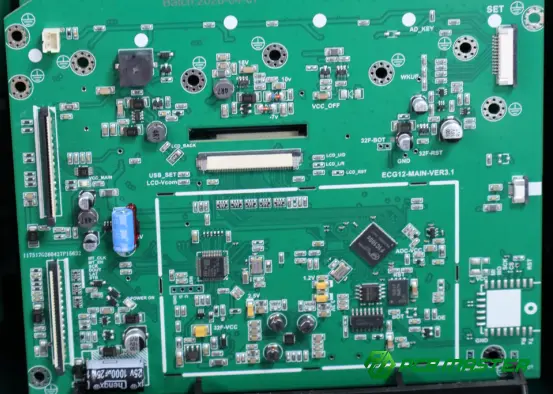
Good LDO power module PCB design should be focused on good component placement, short power paths, clean grounding and good heat management to provide stable voltage output and reliable performance.
PCB Layout Best Practices
The PCB layout of the LDO power module needs to be optimized to reduce noise and voltage drop and provide a stable current path.
The PCB layout is also very important, because the quality of power supply is greatly affected by the LDO power module. Poor layout can cause noise, voltage drops and unwanted heat which can affect system reliability.
The primary PCB layout techniques are:
- Place the LDO module close to the load– Shorter power traces reduce voltage loss and improve response speed.
- Use wide power traces– Wider traces reduce resistance and voltage drop, especially for higher current applications.
- Create a solid ground connection– A continuous ground plane helps reduce electrical noise and improves stability.
- Separate noisy circuits from sensitive circuits– Keep the LDO power section away from high-frequency switching signals.
The sensor PCB layout keeps the LDO power module close to the sensor and has a clean ground plane. It can improve accuracy of measurement , and reduce power noise .
The LDO power module must be correctly laid out on a PCB that provides the stable voltage the circuit expects.
Capacitor Placement
For stability and minimum voltage fluctuation, the input and output capacitors must be placed as close as possible to the LDO power module.
Capacitors play an important role in an LDO circuit. The input capacitor filters the noise of the power supply. The output capacitor also assists the output transient response when the load changes and the voltage stability.
Some good practices in capacitor placement are:
- Place the input capacitor near the LDO input pin– This reduces input voltage fluctuations and prevents instability.
- Place the output capacitor close to the LDO output pin– This helps maintain a stable output voltage.
- Keep capacitor traces short and direct– Long traces add unwanted resistance and inductance.
For example, when the wireless communication module transmits data, the LDO power module can quickly respond to the increased power demand, and avoid the voltage droop if the output capacitor is placed properly.
If the capacitor is placed incorrectly it can cause noise on the output, unstable regulation or unintended circuit behaviour.
Thermal Management
Thermal management in an LDO power module PCB design is all about preventing heat build-up, and spreading heat more effectively with the right copper areas, vias and component choice.
Thermal design is important. In operation, the LDO dissipates the difference between the input voltage and the output voltage as heat, particularly when the difference between the input voltage and the output voltage or the output current is high.
Typical thermal management approaches include:
- Increase copper area around the LDO– Large copper regions help spread heat away from the device.
- Use thermal vias– Vias transfer heat from the top layer to internal or bottom copper layers.
- Select an appropriate PCB material and stack-up– Good thermal characteristics improve heat removal.
- Avoid placing heat-sensitive components nearby– Prevents damage caused by temperature rise.
For example an industrial control PCB that uses an LDO power module to drop 12V to 3.3V will generate more heat than an application that drops 5V to 3.3V. Additional copper area and thermal vias may be required in the case to keep the temperature in a safe operating range.
Effective thermal management enhances the reliability, lifetime and overall performance of LDO power modules and PCB systems.
Where Are LDO Power Modules Commonly Used?
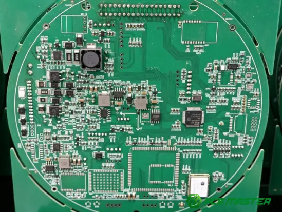
LDO power modules find extensive usage in applications requiring a stable, low noise and reliable power source. These include consumer electronics, industrial and automotive electronics and IoT devices.
Consumer Electronics
LDO power modules are often used in consumer electronics to provide clean and stable power to sensitive components .
Many consumer devices have low voltage circuits which need to be accurately powered. LDO power module converts higher input voltage to stable output voltage. It reduces the power noise which affects the performance of device .
Common uses include:
- Smartphones and tablets– Power small processors, sensors, and communication components.
- Wearable devices– Provide stable power while supporting compact PCB designs.
- Cameras and portable devices– Supply clean voltage for image sensors and control circuits.
For example, a digital camera would have a switching regulator to efficiently convert power and an LDO power module to provide low noise power to the image sensor. Reduces electrical interference and improves picture quality.
Consumer products have to be small, low power and reliable. LDO power modules are a good choice for compact electronic designs.
Industrial and Automotive Systems
DO power modules are widely used in industrial and automotive systems for reliable operation over a wide range of voltages and environmental conditions.
Industrial equipment and automotive electronics often contain electrical noise, voltage fluctuations and temperature variations. We have developed an LDO power module for control circuits and electronic components used in industrial applications, which provides a stable power supply.
Typical application:
- Industrial control systems– Power microcontrollers, sensors, and monitoring circuits.
- Automotive electronics– Supply stable voltage for ECUs, infotainment systems, and sensor modules.
- Factory automation equipment– Support reliable operation of control and communication circuits.
For example, a vehicle’s sensor module could be driven by an unstable vehicle electrical system. This input is conditioned to provide a stable voltage by the LDO power module for accurate sensor data and reliable communication with the system.
These environments demand thermal protection, over-current protection, wide operating temperature ranges and other features that help provide long-term reliability.
Analog, RF, and IoT Devices
LDO power modules are widely used in analogue, RF and IoT devices and provide the low noise power required for accurate signals and stable communications.
Power supply noise easily affects sensitive circuits. A RF and analogue LDO power module is used to reduce voltage variations and electrical noise and to enhance the performance of the system.
Typical applications are:
- RF communication modules– Provide clean power for wireless signal processing.
- Sensor systems– Improve measurement accuracy by reducing power noise.
- IoT devices– Support low-power operation and stable wireless communication.
For example, an IoT device for environmental monitoring may be battery powered. Then, the voltage of the battery is stabilized by LDO power module to provide a stable voltage for sensors and wireless chips, to ensure the accuracy of data collection and communication reliability.
With their low noise characteristics and ease of implementation, the LDO power modules are a key power management solution for the connected and precision electronic devices of today.
What Common Mistakes Should You Avoid When Using an LDO Power Module?
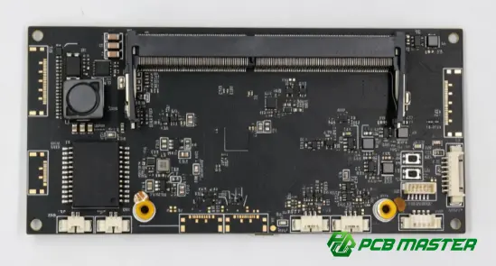
Common design mistakes of LDO power module are wrong capacitors, bad PCB layout and ignoring thermal management. Such problems can result in unstable voltage output, excessive noise or lower product reliability.
Incorrect Capacitor Selection
Bad input/output capacitors can affect stability, noise performance and response speed in an LDO power module.
In an LDO power module circuit, capacitors are important components. The input capacitor is there to filter voltage fluctuations from the power source and the output capacitor is there to maintain a steady output voltage during sudden load changes.
The most frequent errors committed in the selection of capacitors are:
- Using the wrong capacitance value– The LDO may become unstable or produce voltage fluctuations.
- Ignoring capacitor specifications– Parameters such as ESR (Equivalent Series Resistance) can affect regulation performance.
- Placing unsuitable capacitors– Some LDO modules require specific capacitor types for stable operation.
For example, if an IoT device powers a wireless communication chip by an LDO power module, a wrong output capacitor will cause voltage drops during data transmission, which will lead to communication failure.
To prevent this, engineers should take care to always use the values and specifications recommended by the LDO manufacturer for the capacitors.
Poor PCB Layout
A bad PCB layout can affect an LDO power module due to noise, loss of voltage, and EMI.
LDO power module performance is directly related to PCB design. If the power traces, ground or component placement is not designed well, a good LDO can be made to perform poorly
Common PCB Layout Mistakes:
- Long power traces– Increase resistance and create additional voltage drops.
- Poor grounding design– Allows noise to enter sensitive circuits.
- Placing capacitors too far from the LDO– Reduces filtering effectiveness.
- Routing power lines near high-frequency signals– May introduce interference.
For example, in the RF communication PCB, the LDO power module far away from the RF circuit will add the power noise and affect the signal quality.
A good LDO PCB layout requires critical components close together, short current paths and a clean ground plane.
Ignoring Thermal Dissipation
Don't overlook the thermal dissipation in an LDO power module, or you may get overheating, lower efficiency and shorter product life.
An LDO dissipates the extra energy as heat in order to drop voltage. If the difference between the input voltage and output voltage is large or the output current is large, the generated heat will increase.
Typical errors in thermal design are:
- Selecting an LDO without checking power dissipation– The module may exceed its safe temperature range.
- Using insufficient PCB copper area– Limits heat spreading.
- Ignoring operating environment temperature– Causes unexpected overheating in real applications.
For example, the LDO power module of an industrial control board converts the 12V input voltage to 3.3V output voltage, which causes a lot of heat. The module without good copper areas or thermal vias can go into thermal shutdown and interfere the system operation.
Design stage considerations of thermal calculations, appropriate package selection and PCB heat dissipation methods could lead to better reliability.
Conclusion
In a power module, an LDO is an efficient means of providing the low noise, stable power that modern electronic systems require. But that’s just the first step in choosing the right module. However, the right choice of components, PCB layout, capacitor design and thermal management is critical to achieve a reliable performance in real world applications.
Electronics are getting smaller and more powerful. So we need reliable and efficient power solutions. An experienced PCB partner can help ensure that power designs meet the required stability, performance and manufacturing reliability.
With years of experience in PCB manufacturing and engineering support. PCBMASTER helps customers optimize PCB designs for power management applications. This includes layout, choice of materials and quality control in production. With the engineering know-how and advanced manufacturing capabilities, PCBMASTER provides reliable PCB solutions for consumer electronics, industrial systems, automotive electronics and other high performance applications.
FAQs
What is the difference between an LDO power module and an LDO regulator?
The LDO regulator is the main voltage regulation component and is responsible for output voltage regulation and stabilization. The LDO power module is a more complete solution that typically combines the LDO regulator and supporting components such as capacitors, protection circuits and PCB design features.
With the conventional LDO regulator, the engineer must be careful in selecting external components and designing the surrounding circuit. The LDO power module, on the other hand, reduces the design process and provides a ready power solution with fewer external components.
For example, to design a compact IoT device, it is easier to design a PCB and shorten the development cycle by using an LDO power module, because the voltage regulation circuit is integrated.
Can an LDO power module replace a DC/DC converter?
While an LDO power module cannot serve all applications, a DC/DC converter can serve a few applications. There is a trade-off between the power requirements, efficiency goals and noise sensitivity.
When to use LDO power module:
- The voltage difference between input and output is small.
- The required output current is relatively low.
- Low noise and stable voltage are more important than efficiency.
DC/DC converter is generally preferred when:
- High efficiency is required.
- The input and output voltage difference is large.
The system needs higher output power.
For example, a communication module could utilize a DC/DC converter to efficiently step down the battery voltage and an LDO power module to supply clean power to a sensitive RF circuit. The combination provides high efficiency and low noise performance.
How do you calculate power dissipation in an LDO power module?
The power dissipation for an LDO power module is simply the voltage drop across the LDO times the output current.
The basic formula is something like:
Power Dissipation = (Input Voltage - Output Voltage) × Output Current
For example:
- Input voltage: 12V
- Output voltage: 5V
- Output current: 0.5A
Power dissipation:
(12V - 5V) × 0.5A = 3.5W
3.5 watts of power is burning as heat in the LDO power module. The heat may be too much and the module could go into thermal shutdown or reliability could be affected.
Therefore, when designing an LDO power module circuit, engineers should pay attention to PCB copper area, thermal vias, package type and operating environment.
Why are input and output capacitors important for an LDO power module?
Input and output capacitors are important as they help maintain voltage stability, reduce noise and improve the response performance of an LDO power module.
The input capacitor helps:
- Filter voltage fluctuations from the power source.
- Reduce input noise.
- Improve regulator stability.
The output capacitor helps:
- Maintain a stable output voltage.
- Reduce output ripple and noise.
- Support sudden changes in load current.
For instance, if a wireless module suddenly requires more power during a data transfer, the output capacitor will provide the current for a short time, helping to prevent voltage drop.
The type, value and position of the capacitor are very important, because the wrong choice may lead to unstable output or bad performance of the LDO power module.
About the Author

Carol Luo
PCB Design EngineerI'm Carol, a PCB Engineer at PCBMASTER with experience in PCB design and manufacturing engineering since 2018. I focus on translating engineering requirements into reliable PCB solutions, with expertise in stack-up design, material selection, and design-for-manufacturing (DFM). I share practical engineering insights from real-world PCB design and production experience.
Visit Carol Luo's Profile

