








Inductor: What It Is, How It Works, Types, Applications, and PCB Design Considerations
An inductor is a passive electronic component that stores energy in a magnetic field and opposes changes in current. Inductors are widely used in power conversion, filtering, impedance matching, energy storage, EMI suppression, and RF circuits. For PCB designers and electronics manufacturers, selecting the right inductance, current rating, core material, package, and layout is essential for stable electrical and thermal performance. From prototype development to volume production, PCB design and manufacturing capabilities also influence how effectively an inductor-based circuit can be implemented.
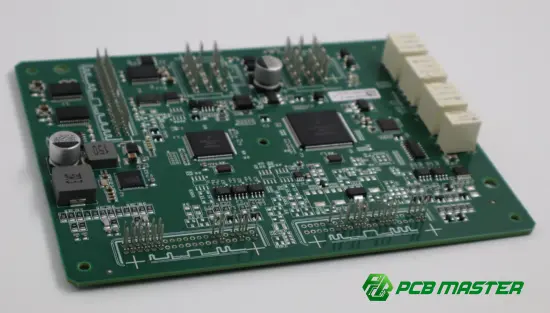
What Is an Inductor?
An inductor is a passive component consisting fundamentally of a conductor, typically formed into a coil or winding. When current passes through the conductor, it generates a magnetic field. The inductor stores energy in this magnetic field and resists rapid changes in current.
The basic relationship is:
V = L × di/dt
Where:
- V = voltage across the inductor
- L = inductance
- di/dt = rate of change of current
Inductance is measured in henries (H) , although practical electronic circuits commonly use microhenries (µH), nanohenries (nH), or millihenries (mH).
The ideal energy stored in an inductor can be expressed as:
E = ½LI²
This characteristic makes inductors particularly important in switching power supplies, DC/DC converters, filters, and energy-storage circuits.
Why Are Inductors Important in Electronics?
Inductors perform several important functions:
- Energy storage in switching power converters
- Current smoothing in power circuits
- Noise and EMI suppression
- Signal filtering
- Impedance matching
- RF circuit tuning
- DC blocking or AC coupling in specific circuit configurations
- Power conversion and regulation
The same basic component can therefore have very different electrical and mechanical requirements depending on the application.
How Does an Inductor Work?
The fundamental behavior of an inductor comes from electromagnetic induction.
When current through the winding changes, the magnetic field also changes. This changing magnetic field generates a voltage that opposes the change in current. This is known as Lenz's law .
For DC:
- Immediately after a DC voltage is applied, current begins to increase.
- The inductor opposes the change in current.
- After the circuit reaches steady state, an ideal inductor behaves approximately like a short circuit.
For AC:
- The inductor continuously reacts to changing current.
- Its opposition to AC is called inductive reactance.
- Inductive reactance is:
Xₗ = 2πfL
As frequency increases, inductive reactance increases.
This frequency-dependent behavior is one reason inductors are widely used in filtering and RF applications.
Common Types of Inductors
Different applications require different inductor structures and magnetic materials.
| Inductor Type | Typical Characteristics | Common Applications |
|---|---|---|
| Air-Core Inductor | No magnetic core; low core loss at high frequency | RF circuits, antennas, tuning circuits |
| Ferrite-Core Inductor | High magnetic permeability and compact size | Power supplies, filtering, EMI suppression |
| Iron-Core Inductor | High inductance and energy-storage capability | Power conversion, low-frequency applications |
| Multilayer Inductor | Compact surface-mount structure | Mobile electronics, high-density PCBs |
| Molded Inductor | Encapsulated magnetic structure | Power management and compact electronics |
| Power Inductor | Designed for relatively high current and energy storage | DC/DC converters, VRMs, battery systems |
| RF Inductor | Optimized for high-frequency electrical characteristics | RF matching, wireless communication |
| Common-Mode Choke | Uses coupled windings to suppress common-mode noise | EMI/EMC filtering |
The appropriate type depends on inductance, operating frequency, current, DC resistance, saturation behavior, package size, temperature, and application requirements .
Key Inductor Specifications You Need to Check
Choosing an inductor based only on its nominal inductance is not sufficient.
1. Inductance
The nominal inductance determines how strongly the component responds to current changes.
Typical values can range from nH to mH , depending on the application.
For a switching regulator, for example, the required inductance depends on switching frequency, input voltage, output voltage, load current, ripple-current requirements, and converter topology.
2. Rated Current
An inductor must handle the expected operating current without excessive heating or unacceptable inductance degradation.
Two current specifications are particularly important:
- Rated current
- Saturation current
Saturation occurs when the magnetic core approaches its magnetic limit. Once the core begins to saturate, inductance can decrease significantly.
3. DC Resistance
DCR (DC resistance) represents the winding's resistance.
Higher DCR causes greater conduction loss:
P = I²R
Therefore, low DCR is often desirable in power applications, particularly when the inductor carries substantial current.
4. Self-Resonant Frequency
Real inductors have parasitic capacitance. As frequency increases, these parasitic effects become increasingly important.
The self-resonant frequency (SRF) is therefore an important parameter in RF and high-frequency applications.
5. Quality Factor
The Q factor indicates how efficiently an inductor stores energy relative to its losses.
High-Q inductors are often desirable in RF and resonant circuits, while power applications may place greater emphasis on saturation current, DCR, thermal performance, and efficiency.
Inductor Applications in PCB Designs
Inductors appear across a wide range of electronic products.
Power Supply and DC/DC Converter
Power inductors are fundamental components in many switching regulators.
A typical buck converter uses an inductor to:
Store energy → release energy → smooth output current
The inductor works together with capacitors and switching devices to convert and regulate voltage efficiently.
This makes inductors particularly important in:
- DC/DC converters
- Point-of-load power supplies
- Voltage regulator modules
- Battery management systems
- Automotive electronics
- Embedded systems
- Industrial control equipment
EMI and Noise Filtering
Inductors and common-mode chokes can attenuate unwanted high-frequency noise.
For example, an EMI filter may combine:
- Inductors
- Common-mode chokes
- Capacitors
- Resistors
- Ferrite components
The PCB layout around these components also affects the effectiveness of the filtering network.
RF and Wireless Circuits
RF inductors are used in:
- Impedance matching
- Resonant circuits
- Oscillators
- RF filters
- Antenna matching networks
- Wireless communication circuits
At high frequencies, parasitic capacitance, pad geometry, trace length, and surrounding copper can significantly affect actual circuit behavior.
Inductor Selection: What Should You Evaluate?
A practical selection process should consider the complete electrical environment rather than simply matching the inductance value.
| Selection Factor | Why It Matters | What to Check |
|---|---|---|
| Inductance | Determines circuit response | Nominal L and tolerance |
| Current | Determines operating capability | Rated and saturation current |
| DCR | Directly affects conduction loss | Maximum DCR |
| Frequency | Determines impedance and losses | Operating frequency and SRF |
| Core Material | Influences magnetic performance | Ferrite, iron, air core, etc. |
| Package | Affects PCB integration | SMD, through-hole, size |
| Temperature | Changes electrical characteristics | Operating temperature range |
| Shielding | Influences EMI behavior | Shielded or unshielded |
| Tolerance | Affects circuit accuracy | Inductance tolerance |
| Height | Matters in compact products | Maximum component height |
The correct inductor is therefore the component that satisfies the complete electrical, thermal, mechanical, and PCB-layout requirements—not simply the one with the correct nominal inductance.
Common Mistakes When Using Inductors on PCBs
Choosing Only by Inductance
A 10 µH inductor is not necessarily interchangeable with another 10 µH inductor.
Their:
- Saturation currents
- DCR
- SRF
- Q factors
- Thermal characteristics
- Physical dimensions
may be substantially different.
Ignoring Saturation
A power inductor can perform correctly during light-load testing but behave differently at higher current if the core approaches saturation.
For power electronics, saturation current should be evaluated against the actual current waveform , not merely the nominal load current.
Using Excessive PCB Trace Length
In switching power circuits, unnecessarily long connections between the inductor, switching device, capacitor, and load can increase parasitic inductance and loop area.
A compact power loop can help reduce unwanted:
- Voltage spikes
- EMI
- Ringing
- Switching losses
Placing High-Current Inductors Without Thermal Consideration
An inductor generates heat through winding resistance and core losses.
PCB designers should therefore consider:
- Copper area
- Thermal spreading
- Component spacing
- Airflow
- Ambient temperature
- Nearby heat sources
Thermal design becomes particularly important in high-current power applications.
PCB Layout Considerations for Inductors
Inductor performance is not determined by the component alone. PCB layout is part of the electrical design.
For switching power circuits, designers commonly pay close attention to the high-current and high-dV/dt loops.
A practical layout strategy includes:
- Keep critical current loops compact.
- Minimize unnecessary trace length.
- Place associated capacitors close to the relevant switching/power nodes.
- Use appropriate copper width and thickness for current.
- Avoid unnecessarily routing sensitive signals close to high-current switching nodes.
- Consider the magnetic field generated by power inductors.
- Provide adequate thermal dissipation.
- Follow the component manufacturer's recommended land pattern.
Inductor vs. Resistor vs. Capacitor
Inductors are frequently discussed together with the other two fundamental passive components.
| Component | Primary Behavior | Energy Storage | Typical PCB Applications |
|---|---|---|---|
| Resistor | Opposes current | No ideal energy storage | Current limiting, voltage division, sensing |
| Capacitor | Opposes voltage changes | Electric field | Decoupling, filtering, energy storage |
| Inductor | Opposes current changes | Magnetic field | Filtering, power conversion, energy storage |
The distinction is particularly useful when analyzing power and filtering circuits.
A capacitor primarily responds to changes in voltage , while an inductor primarily responds to changes in current .
Practical Experience: How to Avoid Inductor-Related PCB Problems
From a PCB manufacturing perspective, an inductor problem is not always caused by the inductor itself. The underlying issue may involve component selection, footprint design, layout, thermal management, or manufacturing constraints.
A practical engineering review should therefore examine the complete chain:
Schematic → Component Selection → Footprint → PCB Layout → Stack-Up → Manufacturing → Assembly → Testing
For example, before manufacturing, an engineering review can identify potential issues such as:
- Incorrect land patterns
- Insufficient copper area
- Inadequate spacing
- Excessive current density
- Difficult-to-manufacture features
- Component placement conflicts
- Thermal concerns
- Potential assembly problems
This is why DFM review before PCB production can be valuable , particularly when an inductor is part of a high-current or high-frequency circuit.
PCBMASTER's PCB Manufacturing and Assembly Capabilities
As a PCB and PCBA manufacturer serving applications across multiple industries, PCBMASTER supports projects where inductors are integrated into power, communication, industrial, automotive, and other electronic systems.
Its manufacturing capabilities cover standard and advanced PCB structures, including HDI , high-frequency PCB , FPC , rigid-flex PCB , and metal core PCB . The company reports production capabilities of up to 100,000 m²/month for HDI PCB, 30,000 m²/month for rigid-flex PCB, 50,000 m²/month for FPC, and 6,000–10,000 m²/month for metal core PCB .
For projects involving inductors, the manufacturing process needs to accommodate the requirements of the complete circuit rather than treating the component as an isolated part.
Engineering File Review
PCBMASTER provides free engineering file checking before production. Engineers review manufacturing considerations and can identify potential design issues before fabrication.
For inductor-based power circuits, this type of review can be useful for examining:
- Component footprints
- Copper routing
- Board structure
- Manufacturability
- Component placement
- High-current areas
Quality and Testing
PCBMASTER states that its products are manufactured under ISO 9001 and IATF 16949 quality management systems , with UL and RoHS certifications .
The company also reports three-time quality inspection, AOI testing, and a 99.5% product yield rate .
For applications where inductors are part of power-management or automotive electronics, manufacturing consistency is particularly important because PCB fabrication and assembly quality can influence the electrical behavior of the finished product.
Prototype to Production
PCBMASTER offers 24-hour rapid PCB prototyping , as well as small-batch and mass-production capabilities.
This prototype-to-production approach allows engineers to validate an inductor-based circuit at the PCB level before moving into larger-scale production.
The key point is that inductor selection, PCB layout, manufacturing, and assembly should be treated as one engineering workflow rather than separate activities.
A Practical Inductor Design Workflow
A reliable development process can be organized into the following steps:
- Define the electrical requirementsDetermine inductance, current, voltage, frequency, ripple current, and temperature requirements.
- Select the inductor technologyChoose the appropriate core material, package, shielding structure, and electrical specifications.
- Verify the manufacturer's specificationsCheck saturation current, DCR, SRF, tolerance, temperature characteristics, and recommended operating conditions.
- Design the PCB footprintFollow the component manufacturer's recommended land pattern and assembly requirements.
- Optimize the PCB layoutPay particular attention to current loops, switching nodes, thermal paths, and sensitive signal routing.
- Conduct DFM and engineering reviewVerify that the PCB can be manufactured and assembled consistently.
- Prototype and testMeasure actual ripple, temperature rise, efficiency, noise, and electrical performance.
- Optimize before volume productionResolve design or manufacturing issues identified during prototype validation.
Final Takeaways
An inductor is much more than a coil on a PCB. Its inductance, saturation behavior, DCR, frequency characteristics, core material, thermal performance, and physical dimensions all influence circuit performance.
For engineers designing an inductor-based PCB, the key considerations are:
- Select the inductor according to the complete electrical operating conditions.
- Check saturation current and DCR rather than relying only on nominal inductance.
- Consider frequency-dependent behavior and parasitic effects in high-frequency circuits.
- Optimize PCB placement and routing, especially in switching power supplies.
- Include thermal considerations for high-current applications.
- Verify the footprint and assembly requirements before production.
- Use engineering and DFM review to identify manufacturability issues early.
- Prototype and test the complete PCB/PCBA before moving to volume production.
As electronic products become more compact and power densities increase, inductor selection and PCB layout will become increasingly interconnected . A manufacturing partner capable of supporting different PCB technologies, engineering review, rapid prototyping, assembly, and production can help reduce the gap between circuit design and a manufacturable product.
Tags: #Inductor #InductorDesign #PCB #PCBA #SMT #PowerElectronics #PCBDesign #DCConverter #EMI #RFDesign #PCBMASTER #ElectronicsEngineering
About the Author

Carol Luo
PCB Design EngineerI'm Carol, a PCB Engineer at PCBMASTER with experience in PCB design and manufacturing engineering since 2018. I focus on translating engineering requirements into reliable PCB solutions, with expertise in stack-up design, material selection, and design-for-manufacturing (DFM). I share practical engineering insights from real-world PCB design and production experience.
Visit Carol Luo's Profile

