








Inductors in Series: Equivalent Inductance, Formula, Applications, and PCB Design Considerations
Inductors in series are connected end-to-end so the same current flows through every inductor. For ideal uncoupled inductors, the total inductance is the sum of the individual inductances. Understanding this relationship is important when designing power supplies, filters, EMI suppression networks, and other PCB circuits. In practical PCB design, however, parasitic resistance, magnetic coupling, saturation, component tolerances, and physical layout can affect the expected result.
What Are Inductors in Series?
Inductors in series are two or more inductors connected sequentially in the same current path. Because there is only one current path, the same current flows through every inductor.
A typical arrangement looks like:
Input → L1 → L2 → L3 → Output
The primary reason for connecting inductors in series is to obtain a higher total inductance than a single available component can provide.
For ideal inductors that are not magnetically coupled, the equivalent inductance is:
L total = L₁ + L₂ + L₃ + … + Lₙ
For example, if a circuit uses:
| Inductor | Inductance |
|---|---|
| L₁ | 10 µH |
| L₂ | 22 µH |
| L₃ | 47 µH |
| Total | 79 µH |
The ideal equivalent inductance is therefore 79 µH .
This principle is straightforward, but real-world PCB designs require additional considerations.
How Do Inductors in Series Work?
An inductor stores energy in its magnetic field when current passes through it. When inductors are connected in series, the current through each component is the same.
The voltage across an ideal inductor is related to the rate of change of current:
V = L × di/dt
With multiple uncoupled inductors in series, the total voltage is the sum of the voltage across each inductor:
V total = V₁ + V₂ + V₃ + …
Since each inductor experiences the same current change, their inductances add together.
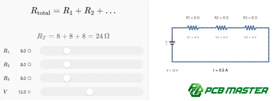
Note: The interactive visualization above illustrates the general series-addition concept using resistors; for inductors, the corresponding ideal relationship is L total = L₁ + L₂ + ….
Example Calculation
Suppose a power circuit requires approximately 100 µH of inductance, but the available components are 47 µH and 56 µH.
Connecting them in series gives:
L total = 47 µH + 56 µH = 103 µH
The nominal inductance is therefore approximately 103 µH , before considering component tolerance, parasitics, and magnetic coupling.
Inductors in Series vs. Inductors in Parallel
Series and parallel connections produce different electrical results.
For ideal, uncoupled inductors:
| Connection | Equivalent inductance |
|---|---|
| Series | L total = L₁ + L₂ + … + Lₙ |
| Parallel | 1/L total = 1/L₁ + 1/L₂ + … + 1/Lₙ |
For two inductors in parallel:
L total = (L₁ × L₂) / (L₁ + L₂)
For example, two 10 µH inductors connected in parallel ideally produce:
L total = 5 µH
The series configuration therefore increases total inductance, while the parallel configuration generally decreases equivalent inductance.
When Is a Series Connection Useful?
Connecting inductors in series can be useful when you need:
- Higher total inductance
- Additional filtering
- EMI and noise attenuation
- A specific impedance characteristic
- A combination of components to achieve a required electrical value
- Flexible component selection when a single inductance value is unavailable
The correct configuration depends on the circuit topology, current level, switching frequency, transient requirements, and available components.
Important Practical Factors
The simple addition formula applies most directly to ideal, uncoupled inductors . Actual components behave differently.
1. DC Resistance
Every practical inductor has winding resistance, commonly specified as DCR.
When inductors are placed in series, their resistances also contribute to the circuit:
R total ≈ R₁ + R₂ + R₃ + …
This additional resistance causes voltage drop and power dissipation.
For a power circuit carrying substantial current, simply selecting inductors based on nominal inductance can therefore be insufficient.
2. Inductor Tolerance
A component marked 10 µH does not necessarily have exactly 10 µH under every operating condition.
The manufacturer's tolerance specifies how much the actual inductance can differ from its nominal value under the stated test conditions.
If several inductors are connected in series, their individual tolerances contribute to the possible range of total inductance.
For example, two nominal 10 µH inductors may have different actual inductance values depending on their specified tolerance and operating conditions.
3. Saturation Current
Saturation is particularly important in power electronics.
As current increases, the effective inductance of some magnetic components decreases because the magnetic core approaches saturation. Therefore, the nominal inductance measured under a particular test condition may not represent the inductance at the actual operating current.
When designing a series inductor network, evaluate:
- Rated current
- Saturation current
- Temperature rise
- DCR
- Inductance versus current
- Core material and construction
The required current rating should be evaluated for the complete series path, not simply the nominal inductance value.
4. Magnetic Coupling
The simple addition formula assumes the inductors are magnetically uncoupled .
If two inductors are physically close enough for significant magnetic coupling, their mutual inductance can change the total effective inductance.
For two coupled inductors, the effective inductance depends on the coupling and winding orientation. Depending on the magnetic relationship, the resulting inductance can differ substantially from the simple arithmetic sum.
This is why PCB placement can matter even when the schematic shows two independent inductors.
5. Parasitic Capacitance
Real inductors also contain parasitic capacitance.
At higher frequencies, an inductor does not behave as a perfect lumped inductance. Its self-resonant frequency becomes important, and the component's impedance can change significantly around and above that region.
Consequently, a series inductor network designed for switching power conversion may require a different analysis from one designed for RF or high-frequency filtering.
How Are Series Inductors Used on PCBs?
Series inductors appear in many electronic circuits and PCB assemblies.
Power Supply Filtering
A series inductor can work with capacitors to form an LC or π filter.
A simplified structure may look like:
Power Source → L → Load
with capacitors connected to ground around the inductive element.
The inductor opposes rapid changes in current, while the capacitor provides a low-impedance path for appropriate AC components.
This makes inductive filtering useful in power conversion and power distribution circuits.
EMI Suppression
Series inductive components can help attenuate unwanted high-frequency current components.
Their effectiveness depends on:
- Inductance
- Impedance versus frequency
- Current rating
- Parasitic characteristics
- Placement
- Return-path design
- Adjacent components
A large nominal inductance does not automatically mean better EMI performance.
DC-DC Converter Circuits
Inductors are fundamental components in many switching power converters.
Depending on the topology, an inductor can store and release energy while helping control current ripple.
In some designs, multiple inductive elements may be used in series to achieve a required electrical or filtering characteristic.
However, designers must evaluate the converter's switching frequency, current ripple, transient response, saturation behavior, and thermal performance together.
Signal and RF Applications
Inductive components can also be used in signal-conditioning and RF networks.
At high frequencies, however, the PCB itself becomes an important part of the electrical system. Trace geometry, spacing, parasitic capacitance, return paths, component packages, and electromagnetic coupling can influence circuit behavior.
For high-frequency PCB projects, component selection should therefore be considered together with the overall stack-up and layout.
Common Mistakes When Using Inductors in Series
Mistake 1: Assuming Inductance Always Adds Exactly
The formula:
L total = L₁ + L₂
is useful for ideal uncoupled inductors, but it is not a complete model of a physical PCB circuit.
Magnetic coupling and frequency-dependent characteristics can change the effective behavior.
Mistake 2: Ignoring DCR
Two inductors may provide the required nominal inductance but introduce excessive resistance.
For power applications, calculate the resulting voltage drop and resistive losses before finalizing the design.
Mistake 3: Checking Only Rated Current
Rated current specifications can have different meanings depending on the manufacturer's test conditions.
For demanding applications, review the actual saturation and thermal characteristics rather than relying on a single current number.
Mistake 4: Treating PCB Layout as Irrelevant
The schematic determines the intended electrical connection, but PCB layout influences parasitic effects and electromagnetic coupling.
For inductors placed in series:
- Avoid unnecessary proximity to sensitive signal traces.
- Consider magnetic-field interaction between neighboring components.
- Keep high-current paths appropriately short and wide.
- Minimize unnecessary loop area where EMI is a concern.
- Follow the component manufacturer's recommended land pattern and layout guidance.
Mistake 5: Selecting Components Only by Inductance
Inductance is only one parameter.
A more complete selection process should consider:
| Parameter | Why it matters |
|---|---|
| Inductance | Determines the nominal inductive behavior |
| Tolerance | Determines possible variation |
| DCR | Affects voltage drop and losses |
| Saturation current | Indicates behavior at higher current |
| Rated current | Relates to thermal limitations |
| Self-resonant frequency | Important for high-frequency operation |
| Package size | Influences PCB layout and thermal behavior |
| Shielding | Can affect electromagnetic coupling |
| Temperature characteristics | Affect performance over operating conditions |
How to Design a PCB With Inductors in Series
A reliable design process should begin before PCB fabrication.
Step 1: Define the Electrical Requirement
Determine the required:
- Total inductance
- Operating current
- Current ripple
- Operating frequency
- Maximum voltage
- Acceptable resistance and power loss
Step 2: Select Appropriate Components
Check manufacturer specifications rather than selecting components solely from nominal inductance.
For power applications, pay particular attention to saturation and thermal performance.
Step 3: Review the Circuit and PCB Layout
Consider the current path, return path, component spacing, copper geometry, and potential magnetic coupling.
Step 4: Perform Engineering Review
Before manufacturing, verify that the component footprints, clearances, assembly requirements, and electrical specifications are compatible with the PCB design.
A manufacturing partner that provides engineering review can identify potential manufacturability issues before fabrication.
Step 5: Validate the Finished PCBA
Testing should verify the actual assembly against the design requirements.
Depending on the application, validation can include electrical testing, functional testing, inspection, and measurements under the intended operating conditions.
PCB Manufacturing Considerations for Inductor Circuits
The inductor itself is only one part of the final design. PCB fabrication and PCBA assembly can influence the performance and reliability of the complete circuit.
For example, power boards may require appropriate copper thickness and thermal design, while high-frequency designs can require controlled impedance, suitable dielectric materials, and carefully managed stack-up structures.
PCBMASTER supports PCB, PCBA, and SMT manufacturing across different electronic applications, including high-frequency PCB , HDI PCB , rigid-flex PCB , FPC , and metal-core PCB requirements. Its engineering service includes free document checking to review manufacturability, PCB performance, and cost considerations before production.
For projects involving inductors in series, this type of engineering review can be particularly useful when component footprints, current-carrying capacity, thermal requirements, or high-frequency layout constraints need to be considered together.
Inductors in Series: Practical Comparison
| Design consideration | Basic calculation | Practical PCB design |
|---|---|---|
| Total inductance | Add individual inductances | Verify actual inductance under operating conditions |
| Current | Same current flows through series components | Check saturation and thermal limits |
| Resistance | Resistances add | Evaluate voltage drop and power dissipation |
| Magnetic interaction | Usually ignored in ideal model | Consider physical placement and coupling |
| Frequency | Ideal inductance model | Consider impedance and self-resonance |
| PCB layout | Not represented in basic formula | Evaluate routing, spacing, return paths, and EMI |
| Manufacturing | Not part of the formula | Verify footprint, assembly, materials, and testing |
Practical Example: Choosing Two Inductors Instead of One
Imagine a PCB design requires an inductive filtering element around a target value that is not readily available as a single standard component.
A designer could investigate whether two inductors connected in series can provide the required nominal inductance.
For example:
L₁ = 33 µH L₂ = 47 µH
Ideal total:
L total = 33 µH + 47 µH = 80 µH
The design should then move beyond the calculation.
The engineer should check whether both inductors can safely carry the required current, whether their combined DCR is acceptable, whether their operating temperatures remain within specification, and whether their physical placement could produce unwanted magnetic coupling.
This illustrates an important PCB engineering principle:
The mathematical equivalent circuit is the starting point—not the complete design.
Frequently Asked Questions About Inductors in Series
Do inductors in series add together?
Yes. For ideal, magnetically uncoupled inductors, the equivalent inductance is the sum of the individual inductances.
Does current remain the same through series inductors?
Yes. Because series components share a single current path, the same current flows through each inductor.
Can I use two inductors in series to replace one larger inductor?
Potentially. The electrical requirements, current rating, DCR, saturation characteristics, frequency behavior, physical size, and magnetic coupling all need to be evaluated first.
Do resistances of series inductors add?
Yes. The winding resistances contribute approximately in series, increasing the total DC resistance of the path.
Do inductors in series increase impedance?
Generally, the inductive reactance increases with inductance at a given frequency according to Xₗ = 2πfL . However, real components also have resistance and parasitic effects, particularly at higher frequencies.
Does PCB layout affect series inductors?
Yes. Component spacing, magnetic coupling, current-loop geometry, trace resistance, parasitic capacitance, and return paths can all affect practical circuit performance.
Are series inductors useful for EMI filtering?
They can be. Their effectiveness depends on the frequency spectrum of the unwanted noise, the inductor's impedance characteristics, current requirements, parasitics, and the complete filter topology.
What is more important: inductance or current rating?
Neither should be considered independently. The design must satisfy both the required inductance and the electrical, thermal, and saturation limits at the intended operating conditions.
Key Takeaways
Inductors in series provide a simple way to increase total inductance when the components are ideal and magnetically uncoupled:
L total = L₁ + L₂ + L₃ + …
But a reliable PCB design requires more than this equation. DCR, saturation current, tolerance, frequency response, self-resonance, magnetic coupling, thermal performance, and PCB layout can all influence the final result.
For engineers developing power supplies, EMI filters, RF circuits, industrial electronics, automotive electronics, or other PCB-based systems, series-inductor selection should therefore be treated as part of the complete circuit and manufacturing design process rather than as an isolated component calculation.
PCBMASTER combines PCB manufacturing, PCBA assembly, SMT, engineering review, and advanced PCB capabilities to support projects from prototype development through production. Its manufacturing capabilities cover standard and advanced PCB technologies for different electronic applications.
Tags
#InductorsInSeries #Inductor #PCBDesign #PCBManufacturing #PCBA #SMT #PowerElectronics #EMI #EMIFilter #CircuitDesign #Electronics #PCBMASTER
About the Author

Carol Luo
PCB Design EngineerI'm Carol, a PCB Engineer at PCBMASTER with experience in PCB design and manufacturing engineering since 2018. I focus on translating engineering requirements into reliable PCB solutions, with expertise in stack-up design, material selection, and design-for-manufacturing (DFM). I share practical engineering insights from real-world PCB design and production experience.
Visit Carol Luo's Profile

