








Inductors in Parallel: Formula, Equivalent Inductance, Current Sharing, and PCB Design Considerations
Inductors in parallel are used when a circuit requires a lower equivalent inductance, higher current capability, or a different impedance characteristic than a single inductor can provide. For ideal, uncoupled inductors connected in parallel, the equivalent inductance follows the reciprocal relationship: 1/L eq =1/L 1 +1/L 2 +…. In practical PCB and power-electronics designs, however, inductor tolerance, DCR, saturation current, magnetic coupling, thermal behavior, and PCB layout must also be considered. A manufacturing partner such as PCBMASTER can support the transition from schematic and component selection to PCB fabrication and PCBA production.
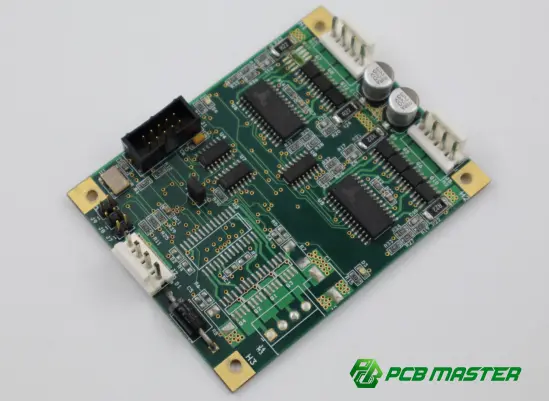
What Are Inductors in Parallel?
Inductors in parallel are two or more inductors connected between the same two electrical nodes. Because they share the same voltage, the total current divides among the individual inductors according to their electrical characteristics.
A simplified arrangement looks like this:
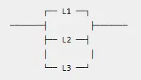
The defining characteristic is that each inductor has the same voltage across it .
For ideal, uncoupled inductors, connecting inductors in parallel reduces the equivalent inductance compared with any individual inductor.
For two inductors:
L eq =(L 1 L 2 )/(L 1 +L 2 )
For three or more inductors:
1/L eq =1/L 1 +1/L 2 +1/L 3 +…
This relationship is analogous to resistors in parallel, although the physical behavior of inductors is considerably more complex in real circuits.
How to Calculate Equivalent Inductance in Parallel
Two Equal Inductors
When two identical inductors are connected in parallel:
L eq =L/2
For example, two 10 µH inductors give:
L eq =(10×10)/(10+10)=5 µH
Therefore, two identical 10 µH inductors in parallel behave like a 5 µH equivalent inductance under the ideal uncoupled model .
Two Different Inductors
Suppose:
- (L1=10µH)
- (L2=22µH)
Then:
L eq =(10×22)/(10+22)≈6.875 µH
The equivalent inductance is therefore lower than either individual inductance.
Three Inductors
For:
- (L1=10µH)
- (L2=10µH)
- (L3=20µH)
1/L eq =1/10+1/10+1/20
Therefore:
L eq =4 µH
This makes parallel inductors useful when a design requires a particular inductance value that is not conveniently available from a single component.
Why Put Inductors in Parallel?
There are several engineering reasons to consider a parallel-inductor configuration.
1. Reduce Equivalent Inductance
The most direct reason is to obtain a lower effective inductance.
For identical inductors:
L eq =L/N
where N is the number of identical inductors connected in parallel.
This can be useful when the desired inductance value is lower than the available standard component value.
2. Increase Current Capability
Parallel inductors can potentially distribute current across multiple components.
For two identical inductors under balanced conditions:
I 1 ≈I 2 ≈I total /2
This can allow each component to carry less current than a single component carrying the entire load.
However, the current rating cannot simply be multiplied by the number of inductors in every practical design . Saturation characteristics, DCR, tolerance, temperature, layout, and transient behavior all influence actual current sharing.
3. Improve Thermal Distribution
Multiple inductors can distribute power dissipation across several physical components.
Instead of concentrating copper loss and magnetic losses in one component, a parallel arrangement may distribute some of the thermal load.
This can be useful in power-conversion circuits where current levels are high and PCB thermal management is important.
4. Use Available Standard Components
A designer may already have a qualified 10 µH inductor available, while the required effective inductance is approximately 5 µH.
Two matching 10 µH components in parallel can provide approximately 5 µH under the ideal uncoupled model.
This can simplify component sourcing, although the BOM cost, PCB area, and assembly cost must also be considered.
What Happens to Current in Parallel Inductors?
The current distribution is one of the most important practical considerations.
Because parallel inductors have the same voltage:
V=L(di/dt)
For ideal inductors subjected to the same voltage, the current behavior depends on their inductance values.
For two inductors:
di 1 /dt=V/L 1
and
Di 2 /dt=V/L 2
Therefore, the lower-inductance branch has a larger current slope under the same applied voltage.
In a steady practical power circuit, DCR and other non-ideal parameters also affect current sharing .
For this reason, simply selecting two inductors with the same nominal inductance does not guarantee perfectly equal current.
DCR Matters When Inductors Are Connected in Parallel
Real inductors have winding resistance, commonly specified as DC resistance (DCR) .
A simplified branch can be represented as:
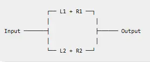
If the inductors have different DCR values, the lower-resistance branch may carry more current.
This creates several design concerns:
- Unequal current distribution
- Different power dissipation
- Different operating temperatures
- Unequal approach to saturation
- Potentially reduced usable current capability
For high-current applications, DCR matching should therefore be evaluated alongside nominal inductance .
Parallel Inductors and Saturation Current
Inductor saturation is another critical consideration.
The rated saturation current indicates the current level at which the inductance begins to decrease significantly according to the manufacturer's specified criterion.
If two inductors are used in parallel, the total current does not automatically become exactly twice the rated saturation current.
For example, using two inductors rated at 5 A does not necessarily mean the combination can safely handle 10 A under every operating condition.
A more realistic evaluation should consider:
- Individual saturation-current specifications
- DCR
- Inductance tolerance
- Temperature derating
- Current imbalance
- Transient current
- PCB copper resistance
- Manufacturer test conditions
The component manufacturer's current-rating definition should always be used when establishing the actual design limit.
Coupled vs. Uncoupled Parallel Inductors
The standard parallel-inductor equation assumes that the inductors are magnetically independent .
This assumption becomes important on a PCB.
If two inductors are physically close to one another, their magnetic fields can interact. Depending on component construction, orientation, spacing, and shielding, this can introduce magnetic coupling.
For strongly coupled inductors, the simple equation
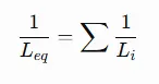
may no longer accurately represent the circuit.
Mutual inductance must then be considered.
For two coupled inductors, the effective relationship depends on:
- L1
- L2
- Mutual inductance M
- Coupling coefficient k
- Winding orientation
- Magnetic-field geometry
Therefore, two physically adjacent inductors should not automatically be treated as perfectly independent components .
Common Design Mistakes
Mistake 1: Assuming Current Ratings Simply Add
Two 5 A inductors do not automatically guarantee a 10 A system rating.
Current sharing must be verified under the actual operating conditions.
Mistake 2: Looking Only at Nominal Inductance
A datasheet value such as 10 µH does not describe the entire component.
Designers should also examine:
- DCR
- Saturation current
- Temperature rise
- Inductance tolerance
- Self-resonant frequency
- Rated current
- Core characteristics
Mistake 3: Ignoring Magnetic Coupling
Component placement can affect magnetic interaction.
This is particularly relevant in compact power-conversion layouts where inductors may be placed close together.
Mistake 4: Treating PCB Layout as Electrically Ideal
At high current, the PCB itself contributes resistance and parasitic inductance.
Unequal trace lengths or copper geometries can cause unequal current distribution between parallel branches.
Mistake 5: Checking Only DC Operation
A circuit may appear acceptable under steady-state current but behave differently during:
- Startup
- Load transients
- Short-duration overload
- Switching transitions
- Power-down events
Transient behavior should be included in validation.
PCB Layout Considerations for Parallel Inductors
Once the circuit has been validated, PCB implementation becomes the next engineering challenge.
A manufacturing-ready PCB layout should account for:
| Design consideration | Why it matters |
|---|---|
| Symmetrical routing | Helps promote more balanced current sharing |
| Short high-current paths | Reduces parasitic resistance and inductance |
| Adequate copper width | Limits PCB conduction losses |
| Thermal copper area | Helps remove heat from the inductors |
| Component spacing | Can reduce unwanted magnetic interaction |
| Ground-plane strategy | Controls return-current paths |
| Via placement | Supports current transfer between copper layers |
| Component orientation | Can influence magnetic coupling and field interaction |
| Keep-out areas | Helps maintain predictable electromagnetic behavior |
| Test points | Simplifies production and engineering verification |
For high-current designs, layout symmetry is not merely an aesthetic consideration. It can directly influence electrical and thermal performance.
How Parallel Inductors Affect PCB Manufacturing
Parallel inductors also introduce manufacturing considerations beyond schematic design.
The PCB designer should consider:
- Component package dimensions
- Land-pattern accuracy
- Copper weight
- Trace width and spacing
- Via current capacity
- Thermal relief
- Component placement
- Reflow profile
- Inspection accessibility
For example, a high-current parallel-inductor circuit may require substantially more copper than a low-current signal circuit.
If the design uses heavy copper, thermal management, HDI structures, rigid-flex construction, or other advanced PCB technologies, these requirements should be reviewed during the engineering stage rather than after PCB fabrication begins.
Engineering File Review Before Production
A manufacturing-ready design should be checked before releasing it to production.
A useful engineering review can examine:
- Component footprint
- Copper geometry
- Current-carrying paths
- Clearance and spacing
- Thermal design
- Stack-up
- Via structures
- Component availability
- Assembly constraints
- Electrical test requirements
This is particularly valuable when parallel inductors are part of a switching regulator, DC/DC converter, battery-management circuit, motor-control system, or other power electronics design.
PCBMASTER provides engineering file review as part of its PCB manufacturing workflow, allowing potential manufacturability and cost issues to be identified before production.
Practical Example: Parallel Inductors in a Power PCB
Consider a power-conversion PCB where the target equivalent inductance is approximately 5 µH, but a qualified 10 µH inductor is already available.
Using two identical 10 µH inductors:
L eq =10µH/2=5µH
The schematic-level solution is straightforward.
However, the engineering review should then examine whether:
- Both inductors have suitable saturation-current ratings
- Their DCR values are sufficiently compatible
- Current sharing is acceptable
- The thermal design is adequate
- Their physical orientation is appropriate
- The PCB copper paths are sufficiently symmetrical
- The switching frequency is appropriate for the selected components
- EMI behavior remains within the project's requirements
This illustrates an important PCB engineering principle: a mathematically correct circuit is not automatically a manufacturing-ready PCB design.
Parallel Inductors vs. a Single Inductor
| Factor | Parallel Inductors | Single Inductor |
|---|---|---|
| Equivalent inductance | Can be reduced | Defined by selected component |
| Current distribution | Shared between branches | Concentrated in one component |
| PCB area | Usually larger | Usually smaller |
| Component count | Higher | Lower |
| Thermal distribution | Can be distributed | Concentrated |
| Current sharing design | Requires evaluation | Generally simpler |
| Magnetic interaction | Must be considered | Usually simpler |
| Assembly complexity | Higher | Lower |
| BOM complexity | Higher | Lower |
| Flexibility | Can use multiple standard values | Depends on available component |
Neither configuration is universally appropriate. The correct choice depends on the electrical, thermal, mechanical, sourcing, and manufacturing requirements of the specific application.
When Should You Consider Parallel Inductors?
Parallel inductors may be worth evaluating when a design requires:
- A lower equivalent inductance
- Higher practical current-handling capability
- Distributed thermal loading
- Multiple standard inductors instead of a specialized value
- A power stage with significant current demand
- A PCB architecture where multiple magnetic components can be accommodated
However, they should be evaluated as a complete electrical and mechanical system rather than simply applying the parallel-inductor formula.
PCBMASTER's Manufacturing Perspective
As a PCB and PCBA manufacturer serving applications across electronics industries, PCBMASTER approaches parallel-inductor designs from both the circuit and manufacturing perspectives.
The company provides PCB, PCBA, and SMT services, supported by ISO 9001, IATF 16949, UL, and RoHS certifications . Its engineering workflow includes document checking intended to identify manufacturability, performance, and cost considerations before production.
For designs involving power electronics, high-frequency circuits , HDI structures , rigid-flex boards , FPCs , and other advanced PCB technologies, manufacturing requirements can influence component placement, routing, stack-up, thermal management, and material selection.
PCBMASTER's capabilities include quick-turn PCB prototyping, advanced PCB manufacturing, PCBA assembly, and engineering support, allowing a parallel-inductor design to be evaluated as part of the broader PCB-to-PCBA production process rather than as an isolated schematic decision.
For example, when a power PCB contains multiple parallel inductors, the engineering review can consider copper distribution, component placement, thermal requirements, manufacturability, and assembly constraints together .
From Circuit Design to Production
A practical workflow for a PCB containing parallel inductors can be structured as follows:
Electrical Requirement
↓
Select Inductance & Current Rating
↓
Evaluate DCR & Saturation
↓
Check Current Sharing
↓
Review Magnetic Interaction
↓
PCB Layout & Thermal Design
↓
DFM / Engineering Review
↓
PCB Prototype
↓
PCBA Assembly
↓
Electrical & Quality Testing
↓
Production
A manufacturing partner with PCB and PCBA capabilities can therefore become part of the engineering process rather than simply receiving the final Gerber files.
Frequently Asked Questions About Inductors in Parallel
What is the formula for inductors in parallel?
For ideal, uncoupled inductors:
1/L eq =1/L 1 +1/L 2 +1/L 3 +…
For two inductors:
L eq =(L 1 L 2 )/(L 1 +L 2 )
Do inductors in parallel reduce inductance?
Yes. For ideal uncoupled inductors, the equivalent inductance is lower than the smallest individual inductance.
Do parallel inductors increase current capacity?
They can distribute current between multiple components , potentially increasing the practical current capability of the circuit. However, current sharing is not automatically equal, so DCR, tolerance, saturation, temperature, and layout must be evaluated.
Do parallel inductors have the same voltage?
Yes. Components connected directly in parallel share the same voltage across their terminals.
Does DCR matter for parallel inductors?
Yes. Different DCR values can cause unequal current sharing and different power dissipation between the branches.
Can two identical inductors always be placed in parallel?
Not necessarily. The circuit designer should verify electrical ratings, current sharing, thermal performance, magnetic interaction, PCB layout, and application requirements before doing so.
Are parallel inductors useful in DC/DC converters?
They can be used in power-conversion designs where lower effective inductance, current distribution, or thermal distribution is desirable. The appropriate configuration depends on the converter topology and operating requirements.
Can PCB layout affect current sharing?
Yes. Unequal trace resistance, via resistance, copper geometry, and routing can contribute to unequal current distribution between parallel branches.
Conclusion
Inductors in parallel provide a practical method for obtaining lower equivalent inductance and distributing current across multiple magnetic components. The ideal calculation is straightforward, but real PCB designs require considerably more analysis.
The key factors include:
- Equivalent inductance
- DCR
- Saturation current
- Current sharing
- Temperature rise
- Magnetic coupling
- Switching frequency
- PCB copper geometry
- Thermal management
- Manufacturing constraints
For simple circuits, the parallel-inductor equation may be sufficient for an initial calculation. For power electronics and production PCBs, however, component selection, electrical behavior, PCB layout, thermal design, and manufacturing requirements should be evaluated together .
This is where engineering review and PCB manufacturing expertise become important. PCBMASTER combines PCB fabrication, PCBA assembly, SMT, engineering file review, and advanced PCB capabilities to support projects from prototype development through production.
Tags: #InductorsInParallel #Inductor #PCBDesign #PCBA #PowerElectronics #PCBLayout #CircuitDesign #SMT #PowerSupply #DCConverter #PCBManufacturing #PCBMASTER #EngineeringInsights
About the Author

Carol Luo
PCB Design EngineerI'm Carol, a PCB Engineer at PCBMASTER with experience in PCB design and manufacturing engineering since 2018. I focus on translating engineering requirements into reliable PCB solutions, with expertise in stack-up design, material selection, and design-for-manufacturing (DFM). I share practical engineering insights from real-world PCB design and production experience.
Visit Carol Luo's Profile

