








Kapitel 01
Was ist ein PCB-Prototyp und was sollte er validieren?
Ein PCB-Prototyp ist eine physische Leiterplatte, die aus Ihren Konstruktionsdateien hergestellt wird-bevor Sie sich zu Produktionsmengen verpflichten. Es verwandelt ein digitales Design in eine echte Platine, die unter tatsächlichen Betriebsbedingungen zusammengebaut, gemessen und getestet werden kann, so dass Designprobleme eher früh als im Hochfahren der Fabrik auftreten.
Bevor die Fertigung beginnt, verdienen mehrere Faktoren eine technische Überprüfung: Schichtaufbau, Materialauswahl, Leiterbahngeometrie, Durchgangsstrukturen, Impedanzanforderungen und Bauteilplatzierung. Hier zahlt sich ein Design for Manufacturability (DFM) -Assessment aus. Bei PCBMASTER überprüfen erfahrene Ingenieure diese Punkte mit Ihnen vor der Fertigung, so dass der Prototyp, den Sie erhalten, bereits an der Art und Weise ausgerichtet ist, wie die Platine letztendlich hergestellt wird.
Sobald der Prototyp hergestellt ist, können Sie mit der Komponentenmontage und Funktionstests fortfahren, um Konstruktionsfehler zu identifizieren und gezielte Änderungen vorzunehmen. Dieser einzelne Loop – Design, Prototyp, Test, Verfeinerung – bildet die Grundlage für jede nachfolgende Entwicklungsstufe.
Schlüssel Takeaways
Was ein Prototyp häufig verwendet wird, um zu überprüfen
Erste Prototypen werden in der Regel verwendet, um die folgenden Aspekte zu validieren-die Prioritätsreihenfolge hängt von Ihrem Produkttyp ab:
-
1
Elektrische Leistung
Funktionalität, Signalintegrität, Leistungsintegrität.
-
2
Komponenten & Mechanische Passform
Platzierung, Platzbedarf, Einschließungssitz.
-
3
Thermische Eigenschaften
Wärmeableitung und Betriebstemperaturen.
-
4
Herstellbarkeit
Ob das Design zuverlässig im Maßstab hergestellt werden kann.
Beispielsweise erfordern Hochgeschwindigkeitsdesigns möglicherweise eine größere Aufmerksamkeit auf Impedanz und Signalintegrität, während flexible Leiterplatten (FPCs) für Wearables Biegetests und Umweltbeständigkeitstests erfordern. Die breiten Fertigungskapazitäten von PCBMASTER unterstützen verschiedene Prototyping-Techniken und Materialstrukturen und helfen Ihnen, Ihr Design gegen die beabsichtigten Anforderungen zu validieren.
Prototyp schneller, Validierung früher.
Unsere Ingenieure überprüfen Ihre Dateien vor der Fertigung und können bestimmte Prototypen innerhalb von 24 Stunden produzieren.
Kapitel 02
Warum PCBMASTER für Leiterplatten-Prototypen wählen
Hardware-Teams wählen einen Prototyp-Partner basierend auf Geschwindigkeit, Leistungsfähigkeit und Vertrauen. Diese sechs Vorteile definieren, wie PCBMASTER Ingenieure vom ersten Board bis zum ersten Produktionslauf unterstützt.
24 Stunden Rapid Prototyping
Wenn die Entwicklungspläne eng sind, macht ein schneller Turnaround den Unterschied zwischen einem eingehaltenen Termin und einem verzögerten Start aus.
Erweiterte PCB-Fähigkeit
1 – 64 Schichten, HDI, Hochgeschwindigkeits- und Hochfrequenzplatten, FPC, Starrflex, Keramiksubstrate, IC-Substrate und mehr.
50 + Ingenieure im Support
Technischer Support, wenn Anforderungen komplex werden – Stapelprüfung, Materialberatung und Feedback zur Herstellbarkeit.
Starke Materialversorgung
Schneller Zugriff auf eine breite Palette von Laminatmaterialien für vielfältige technische und anwendungstechnische Anforderungen.
Prototyp → Massenproduktion
Fahren Sie mit demselben Hersteller von validierten Prototypen bis hin zur Kleinserien- und Volumenproduktion fort.
PWB + PCBA One-Stop
Vom Rohkarton bis zum funktionalen Prototyp – Komponentenbeschaffung, SMT/THT-Montage und Tests an einem Ort.
Kapitel 03
PCB-Prototyp-Fähigkeiten: 12 Board-Typen, ein Lieferant
Nicht alle Prototypen sind gleich. Eine einfache zweischichtige FR-4-Platine benötigt möglicherweise nur einen Standard-Workflow, während HDI-, Hochfrequenz-, flexible oder Hochkupfer-Designs spezielle Materialien und Prozesse erfordern. Die folgenden zwölf Leiterplattentypen decken das Spektrum der Prototypanforderungen ab, die PCBMASTER unterstützt.

1-64 Schicht-Mehrschichtplatten
Standardmäßige bis hochkomplexe Schichtstapel für Computer-, Telekommunikations- und Industriesysteme.

HDI-Leiterplatten
Blind- und Buried Vias, Microvias, Any-Layer-Interconnects für dichte Designs.

Hochgeschwindigkeits-/Hochfrequenz-Leiterplatten
Kontrollierte Impedanz und verlustarme Materialien für Hochfrequenz- und Hochgeschwindigkeitsverbindungen.

FPC (Flexible Schaltungen)
Ultradünne flexible Platinen für Wearables, medizinische und kompakte Geräte.

Starr-Flex-Platten
Starre und flexible Schichten kombiniert in einer Karte für 3D-Integration.

Keramisches Substrat PCBs
Substrate mit hoher Wärmeleitfähigkeit für Leistungs- und LED-Module.

IC-Substrate
Feinlinien-Substrate für Chipverpackungen und fortschrittliche Module.

Schwere Kupferplatten
Dicke Kupferschichten für Hochstromanwendungen.

Backplane und Server-Boards
Großformatige High-Layer-Boards für die Rechenzentrumsinfrastruktur.

Embedded/IoT-Module
Kompakte Boards für Edge Computing, Sensing und Konnektivität.

Metallbasen/Kühlplatten
Aluminium- und Kupferplatten für das Wärmemanagement.

Antennenplatinen
Hochfrequenzantenne und HF-Frontend-Prototypen.
Standard Prototyp Spezifikationen
Eine Referenzansicht der Parameter, die PCBMASTER bei Prototypenaufträgen unterstützen kann. Ihre projektspezifischen Anforderungen werden mit unserem Engineering-Team vor der Produktion bestätigt.
| Parametrierung | Typische Optionen |
|---|---|
| . | 1 – 64 Schichten, besonders angefertigt |
| Werkstoffe | FR-4/High-Tg FR-4/Rogers/PTFE/Aluminium/Polyimid/Keramik |
| PCB-Typ | Starr/Flex/Starr-Flex/HDI/Hochfrequenz/High-Speed/Metallkern/Keramik/Schweres Kupfer |
| Die dicke Von kupfer | Maßgeschneidert |
| Brett-Stärke | Maßgeschneidert |
| Diese glatte oberfläche | HASL/ENIG/OSP/Immersionszinn/etc. |
| Minimale Eigenschaft | Nach PCB-Technologie |
| Via Typ | Durch/blind/begraben/Microvia |
| Impedanzkontrolle | Verfügbar |
| Lötmaske | Grün/Schwarzes/Blau/Rot/Gelb/Weiß/etc. |
| Seide, druck. | Maßgeschneidert |
| Testen | Elektrische/fliegende Sonde/AOI/andere verfügbare Tests |
Sie sind sich nicht sicher, welche Technologie Ihr Design benötigt?
Senden Sie uns Ihre Konstruktionsunterlagen – unsere Ingenieure werden Ihnen die richtige Prototyplösung empfehlen.
Kapitel 04
Wie man einen PCB-Prototyp bestellt: 5 Schritte
Die Bestellung eines Leiterplattenprototyps von PCBMASTER folgt einem einfachen Weg von Ihren Designdateien zu getesteten Boards. Hier ist, wie der Prozess funktioniert.
-
01
Laden Sie Ihre Dateien hoch
Gerber-Dateien, Zeichnungen, Stücklisten und Ihre Projektanforderungen einreichen.
-
02
Ingenieurprüfung
Unsere Ingenieure überprüfen Fertigungsanforderungen und Spezifikationen und kennzeichnen mögliche Probleme vor der Fertigung.
-
03
Angebot & Bestätigung
Erhalten Sie ein projektspezifisches Angebot und bestätigen Sie die Produktionsdetails, bevor wir beginnen.
-
04
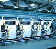
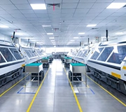
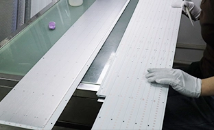
Prototypenfertigung
PCBMASTER fertigt und inspiziert Ihre Prototypenplatinen – in nur 24 Stunden für qualifizierende Projekte.
-
05
Testen & Skalieren
Validieren Sie das Design und gehen Sie dann mit demselben Fertigungspartner in Richtung Kleinserien- oder Massenproduktion über.

Kapitel 05
Anwendungen & Praxisbeispiele für Prototypen
Von High-Speed-Computing und Automobilelektronik bis hin zu Wearables und Energiesystemen variieren die Anforderungen an Prototypen je nach Anwendung. Die folgenden acht Sektoren repräsentieren die Bandbreite der Projekte, die PCBMASTER unterstützt – gefolgt von vier Fallstudien, die zeigen, wie bestimmte Herausforderungen in der Fertigung gelöst wurden.
KI & Informatik
Hochgeschwindigkeits-Leiterplatten zur Validierung der Signalintegrität, der thermischen Leistung und der Systemintegration.
Automobilelektronik
BMS, Steuerung, Sensor und EV-Elektronik vor der Produktion validiert.
Industrielle Steuerung
Steuerungs-, Automatisierungs- und Überwachungsschaltungen, die vor der Bereitstellung getestet wurden.
Kommunikationssysteme
Hochgeschwindigkeits- und Hochfrequenzausführungen für zuverlässige Übertragung validiert.
Medizinische Elektronik
Leistungs-, Zuverlässigkeits- und Konstruktionsanforderungen vor der Produktion überprüft.
Leistungselektronik
Leistungsumwandlung, thermische Leistung und frühzeitig validierte Regelkreise.
Erneuerbare Energien
Energiemanagement- und Energiespeicherdesigns vor der Skalierung getestet.
Unterhaltungselektronik
Kompaktes Design, Funktionalität und mechanische Passform vor der Produktion validiert.
Von Bewerbungsvoraussetzungen zu Projekten in der realen Welt
Vier Projekte, die zeigen, wie fortschrittliche Fertigungskapazitäten zu gelösten technischen Problemen führen. Auf dem Desktop werden alle vier Fälle als statische Zeile dargestellt; auf dem Mobilgerät scrollen sie als Karussell-jeder Fall bleibt vollständig lesbar auf der Seite.
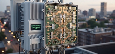
 Case 01 · 5G Kommunikation
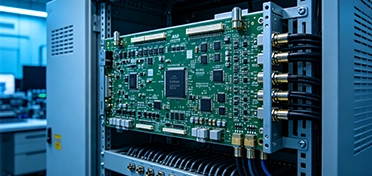
32-lagiges AAU Modul
32 Schichten · 432 × 356 × 3,2 Millimeter · μm ≤ 75 Hinterbohrungs-Stub
Ein Unternehmen für 5G-Kommunikationsausrüstung benötigte eine großformatige, hochintegrierte Leiterplatte für eine aktive Antenneneinheit. PCBMASTER fertigte eine 32-Schicht-Platine mit 432 × 356 × 3,2 mm, die achtundzwanzig 0402 Kondensatoren und sechzehn 0201 Widerstände integrierte. Um die Signalintegrität aufrechtzuerhalten, wurden die Bohrstummel auf ≤ 75 μm kontrolliert, wobei die Zuverlässigkeitsüberprüfung der Klasse 3 1.000 thermische Zyklen und 1.000 Stunden CAF-Tests enthielt – was einen reibungsloseren Übergang zur Serienfertigung unterstützt.
32 Schichten · 432 × 356 × 3,2 Millimeter · 28 × 0402 Kappen · 16 × 0201 Widerstände · μm Stub ≤ 75
 Case 02 · RF und Kommunikation
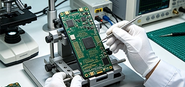
MmWave Antennenmodul
20/20 μm L/S · Rogers 4350B + FR-4 · mSAP-Technologie
Ein Unternehmen für drahtlose Kommunikationsausrüstung, das ein mmWave-Antennenmodul entwickelte, benötigte ein feines Routing und zuverlässige Hochfrequenzleistung. PCBMASTER setzte mSAP-Technologie für 20 μm Linienbreite/-abstand ein und kombinierte Rogers 4350B mit FR-4 in einem Hybrid-Stack-up und platzierte das Hochfrequenzmaterial dort, wo die elektrische Leistung am wichtigsten war. Eine eingebettete Kondensatoranordnung von 0,1 μF/cm ² trug dazu bei, das Leistungsgeräusch zu reduzieren und die Signalstabilität zu verbessern – um elektrische Leistung und Herstellbarkeit auszugleichen.
20 μm L/S · Rogers 4350B + FR-4 · 0,1 μF/cm ² Eingebettetes Kondensator-Array
 Case 03 · Unterhaltungselektronik
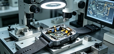
Flaggschiff-Smartphone-Motherboard
10 Schichten Any-Schicht HDI · 50/50 μm L/S · ± 8% Über kupferne Einheitlichkeit
Ein Unterhaltungselektronikunternehmen, das ein Flaggschiff-Smartphone-Motherboard entwickelte, benötigte eine dichte Schaltung in einer kompakten Struktur. PCBMASTER produzierte eine 10-lagige Any-Layer-HDI-Leiterplatte mit 50 μm/50 μm Linienbreite/Abstand. Die Pulse Periodic Reverse (PPR) -Beschichtung erreichte ± 8% über die Gleichmäßigkeit der Kupferdicke bei einer Abscheiderate von 1,5 μm/min, was ein kompaktes, hochdichtes HDI-Design mit größerer Fertigungskonsistenz für den Übergang zur Produktion validiert.
10 Schichten Any-Schicht HDI · 50/50 μm L/S · ± 8% Über kupferne Einheitlichkeit · 1,5 μm/min
 Case 04 · Tragbare Elektronik
Intelligenter Ring FPC
0,1 Millimeter Stärke · 200.000 Biegungszyklen · 1,2 Millimeter Biegungsradius
Ein tragbares Elektronikunternehmen, das einen intelligenten Ring entwickelte, brauchte eine ultradünne flexible Schaltung, die wiederholtem Biegen standhält. PCBMASTER entwickelte einen FPC mit nur 0,1 mm Dicke und validierte Flexibilität durch 200.000 Biegezyklen bei einem Biegeradius von 1,2 mm. Tests über -20 ° C bis 60 ° C halfen dem Kunden, den FPC unter wiederholter mechanischer Belastung und unterschiedlichen Temperaturen zu bewerten, was Vertrauen vor der Massenproduktion bot.
0,1 Millimeter Stärke · 200.000 Biegungszyklen · 1,2 Millimeter Radius · − 20 ° C zu 60 ° C
Kapitel 06
Zertifizierte Qualität & Was Ingenieure sagen
Zertifizierungen bilden die Basis für konstante Qualität; Kundenstimmen zeigen, wie sich die Arbeit mit PCBMASTER in einem Projekt tatsächlich anfühlt. Beide gehören in dasselbe Kapitel, weil sie die gleiche Frage beantworten: Kann man diesem Partner ein Board anvertrauen, das zählt?
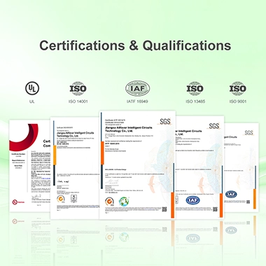
ISO 9001
Qualitätsmanagementsystem
IATF 16949
Automotive Qualitätsstandard
Impressum
Produktsicherheitszertifizierung
RoHs
Gefahrstoffkonformität
In den Worten der Ingenieure
Drei Kunden, drei verschiedene Phasen des Produktlebenszyklus – Geschwindigkeit, Engineering-Tiefe und Kontinuität.
Wir arbeiteten gegen einen sehr engen Entwicklungsplan und benötigten Prototypenplatinen so schnell wie möglich. PCBMASTER fertigte unsere Leiterplatten innerhalb von 24 Stunden, was unserem Team einen viel früheren Start beim Testen und Debuggen ermöglichte.

Michael Turner, Geschäftsführer
Hardware Engineering Manager · Unterhaltungselektronik · Vereinigte Staaten
Produkt: Unterhaltungselektronik-Kontrollorgane
Das Board selbst war nicht einfach – mehrschichtiges HDI, spezifische Stack-up-Anforderungen, Materialüberlegungen. Was ich schätzte, war, dass die Ingenieure von PCBMASTER sich diese Details anschauten, anstatt die Dateien einfach zu verarbeiten. Ihr Feedback hat uns geholfen, Herstellbarkeitsprobleme frühzeitig zu identifizieren und den Prototypenprozess viel reibungsloser zu gestalten.

Daniel Weber, Geschäftsführer
Leitender Leiterplatten-Konstrukteur · Industrieelektronik · Deutschland
Produkt: Mehrschichtige HDI-Kontrollorgane
Wir kamen ursprünglich für Prototypen zu PCBMASTER, aber die Beziehung endete nicht hier. Nachdem das Design validiert wurde, setzten wir mit der Kleinserienproduktion fort und erhöhten später unsere Volumina. Die Tatsache, dass wir während dieser Phasen nur einen Lieferanten hatten, hat uns vor der Wiederholung technischer Gespräche mit einem neuen Hersteller bewahrt – diese Kontinuität war ein großer Vorteil.

James Andersen
Einkaufsleiter · Industrielle Automatisierung · Großbritannien
Produkt: Industrielle Steuerung PWB
Kapitel 07
Prototyping-Wissen: Sechs Dinge, die jeder Ingenieur berücksichtigen sollte
Ein Leiterplatten-Prototyp ist nicht nur eine physische Probe – er ist ein entscheidender Schritt hin zu einem herstellbaren, validierten Produktionsdesign. Diese sechs Themen decken die Grundlagen ab, die wir am häufigsten mit Kunden besprechen.
1. Vom PCB-Design zum physischen Prototyp▾
Das Leiterplatten-Prototyping verwandelt Ihr digitales Design in eine physische Leiterplatte, die unter realen Bedingungen getestet werden kann. Vor der Fertigung sollten kritische Faktoren wie Schichtaufbau, Materialien, Leiterbahngeometrie, Durchkontaktierungen, Impedanzanforderungen und Bauteilplatzierung durch eine Design for Manufacturability (DFM) -Bewertung überprüft werden. Bei PCBMASTER helfen erfahrene Ingenieure, potenzielle Fertigungsprobleme zu identifizieren, bevor die Fertigung beginnt.
Sobald der Prototyp hergestellt ist, können Sie mit der Komponentenmontage und Funktionstests fortfahren, um Konstruktionsfehler zu identifizieren und gezielte Änderungen vorzunehmen. Dieser Prozess legt den Grundstein für die nächste Entwicklungsstufe.
2. Welche Aspekte sollte ein PCB-Prototyp validieren?▾
Ein Prototyp macht mehr als nur die Herstellbarkeit zu überprüfen. Erste Prototypen werden typischerweise zur Validierung der elektrischen Leistung, der Bauteilplatzierung, der mechanischen Passform, der thermischen Eigenschaften, der Signalintegrität und der Herstellbarkeit verwendet. Die spezifischen Validierungsprioritäten hängen von Ihrem Produkttyp ab.
Beispielsweise erfordern Hochgeschwindigkeitsdesigns möglicherweise eine größere Aufmerksamkeit auf Impedanz und Signalintegrität, während flexible Leiterplatten (FPCs) für Wearables Biegetests und Umweltbeständigkeitsprüfungen erfordern. Die breiten Fertigungskapazitäten von PCBMASTER unterstützen verschiedene Prototyping-Techniken und Materialstrukturen und helfen Ihnen, Ihr Design gegen die beabsichtigten Anforderungen zu validieren.
3. Prototyp-Iteration: Warum der erste Prototyp oft nicht das endgültige Design ist▾
Initiale Leiterplatten-Prototypen zeigen häufig Probleme auf, die allein durch Konstruktionsdateien oder Simulationen nicht vollständig erkannt werden können, z. B. Probleme mit Bauteilabstand, thermischen Eigenschaften, Signalleistung, mechanischer Montage oder Fertigungstoleranzen. Folglich ist Prototypiteration ein Standardteil der Hardwareentwicklung.
Die Rapid Prototyping-Services von PCBMASTER verkürzen die Lücke zwischen Designänderungen und physischer Verifizierung und helfen Ihnen, Probleme früher zu identifizieren und das Design vor der Produktion zu verfeinern.
4. Prototyp-Leiterplatten vs. Massenproduktion von Leiterplatten: Was ist der Unterschied?▾
Während Prototypen- und Massenproduktions-Leiterplatten möglicherweise das gleiche grundlegende Design teilen, verschieben sich die Anforderungen an die Fertigung, wenn die Produktion steigt. Prototyping priorisiert in der Regel Geschwindigkeit, Designvalidierung und technische Iteration, während die Massenproduktion sich auf Prozessstabilität, Materialkonsistenz, Ertrag, Kosten und Lieferkontinuität konzentriert.
PCBMASTER berücksichtigt die Anforderungen der Massenproduktion während der Prototyping-Phase und hilft Ihnen, Designentscheidungen zu vermeiden, die während des Prototypenbaus funktionieren könnten, aber Probleme bei der Kleinserien- oder Großserienfertigung verursachen.
5. Wie sich die Komplexität von Leiterplatten auf Prototyping-Strategien auswirkt▾
Nicht alle Leiterplatten-Prototypen erfordern die gleichen Herstellungsverfahren. Während eine einfache zweischichtige FR-4-Platine möglicherweise nur einen Standard-Fertigungsworkflow benötigt, erfordern Designs mit HDI (High-Density Interconnect), Mehrschichtstrukturen, Hochgeschwindigkeits-/Hochfrequenzschaltungen, FPCs (Flexible Printed Circuits), Starrflex-Platinen oder schwerem Kupfer spezielle Materialien und Prozesse.
Mit zunehmender Komplexität des Designs werden Faktoren wie Stapelstruktur, Impedanzkontrolle, Mikrovia-Technologie, Feinlinienführung, Materialverfügbarkeit und Fertigungstoleranzen immer kritischer. PCBMASTER unterstützt eine breite Palette von Leiterplattentechnologien und ermöglicht es Ihnen, die richtige Prototyping-Lösung auf der Grundlage der technischen Anforderungen Ihres Produkts auszuwählen-ohne Kompromisse bei komplexen Designs, die zu Standard-Fertigungsworkflows passen.
6. Was definiert einen "produktionsbereiten" Leiterplatten-Prototyp?▾
Ein serienreifer Prototyp muss über die grundlegende Funktionalität hinausgehen; er erfordert die Berücksichtigung von Herstellbarkeit, Materialauswahl, Stapelstruktur, Toleranzkontrolle, Komponentenintegration, Zuverlässigkeit und Skalierbarkeit. Bei PCBMASTER berücksichtigen wir die Anforderungen für die anschließende Kleinserien- und Massenproduktion bereits beim Prototyping.
Dies hilft Ihnen, potenzielle Fertigungsrisiken frühzeitig zu erkennen und unnötige Konstruktionsänderungen zu minimieren, wenn die Produktion skaliert. Unser Ziel ist es nicht nur, einen funktionalen Prototypen zu erstellen, sondern ein validiertes Design zu entwickeln, das einen reibungsloseren Übergang in die Massenproduktion unterstützt.
Kapitel 08
Häufig gestellte Fragen
Antworten auf die Fragen, die Ingenieure und Beschaffungsteams am häufigsten stellen – von Kosten und Vorlaufzeit bis hin zur Dateiprüfung und zum Produktionsübergang.
Ja.-Ja. PCBMASTER unterstützt eine breite Palette von PCB-Prototyping-Anforderungen, von Standard-Einzel- und doppelseitigen Platinen bis hin zu Multilayer-, HDI-, High-Speed-/Hochfrequenz-, FPC-, Starrflex-und Schwerkupferplatinen. Sie können Materialien, Schichtanzahl, Kupferdicke, Oberflächenbeschaffenheit, Impedanzanforderungen und andere technische Details angeben. Unser Engineering-Team überprüft Ihre Anforderungen vor der Produktion und empfiehlt eine geeignete Fertigungslösung.
Die Kosten für Leiterplatten-Prototypen hängen von Faktoren wie Abmessungen, Menge, Schichtzahl, Materialien, Kupferdicke, Oberflächenbeschaffenheit, Herstellungsprozessen und Designkomplexität ab. Fortschrittliche Anforderungen, einschließlich HDI, Feinleitungsschaltungen, Impedanzkontrolle oder Spezialmaterialien, können sich auch auf den Preis auswirken. PCBMASTER bietet projektspezifische Angebote, die auf Ihren tatsächlichen Konstruktionsdateien und Anforderungen basieren, und hilft Ihnen, die Herstellungskosten vor der Auftragserteilung zu verstehen.
Abhängig von den Leiterplattenspezifikationen, der Menge, den Materialien und den Herstellungsanforderungen kann PCBMASTER bestimmte Leiterplattenprototypen in nur 24 Stunden fertigstellen. Darüber hinaus dauert der internationale Versand in der Regel weitere 3 – 6 Werktage, je nach Bestimmungsort und Versandservice. Stellen Sie für dringende Projekte Ihre PCB-Dateien und Spezifikationen zur Verfügung, damit unser Team den schnellstmöglichen Produktionsplan bewerten kann.
In der Regel müssen Sie Gerber-Dateien mit der erforderlichen Menge, den Abmessungen der Platine, der Schichtanzahl, den Materialien, der Kupferdicke, der Oberflächenbeschaffenheit und allen speziellen Herstellungsanforderungen bereitstellen. Falls verfügbar, können Bohrdateien, Stapelinformationen, Impedanzanforderungen und andere technische Dokumentation ebenfalls hilfreich sein. Komplette Spezifikationen ermöglichen es PCBMASTER, Ihre PCB-Prototypanforderungen genauer zu bewerten und ein genaueres Angebot zu erstellen.
Ja.-Ja. PCBMASTER bietet technische Unterstützung vor der Herstellung von Leiterplattenprototypen. Unsere Ingenieure können wichtige Fertigungsüberlegungen überprüfen, einschließlich Stapelung, Materialien, Leiterbahnbreite und -abstand, Durchkontaktierungen, Impedanzanforderungen und Gesamtfertigbarkeit. Die Identifizierung potenzieller Probleme vor der Fertigung kann Ihnen helfen, unnötige Prototyp-Revisionen zu vermeiden, Fertigungsrisiken zu reduzieren und effizienter von Design-Dateien zu physischen Leiterplatten-Prototypen zu wechseln.
PCBMASTER wendet technische Überprüfungen, kontrollierte Fertigungsprozesse sowie Inspektions- und Testverfahren während des gesamten PCB-Produktionszyklus an. Abhängig von den Projektanforderungen kann die Qualitätskontrolle Maßgenauigkeit, visuelles Aussehen, elektrische Leistung, Beschichtung und andere spezifizierte Kriterien abdecken. PCBMASTER arbeitet unter den Qualitätsmanagementsystemen ISO 9001 und IATF 16949 und führt Tests vor dem Versand durch, um sicherzustellen, dass Ihre Leiterplatten-Prototypen die vereinbarten technischen und Qualitätsanforderungen erfüllen.
Ja.-Ja. PCBMASTER kann Ihr Prototypenprojekt über die Bare-Board-Fertigung hinaus auf Komponentenbeschaffung, SMT/THT-Montage und Tests erweitern. Dies bietet Ihnen einen integrierten Weg von der Leiterplattenfertigung zu einer funktionalen PCBA, ohne mehrere Lieferanten zu koordinieren. Durch die Kombination dieser Dienstleistungen vereinfacht PCBMASTER das Lieferantenmanagement und verkürzt den Weg von der Leiterplatten-Prototypenfertigung bis hin zur Funktionsprüfung.
Ja.-Ja. PCBMASTER unterstützt den Übergang vom Leiterplatten-Prototyping zur Kleinserien- und Massenproduktion. Produktionsüberlegungen – einschließlich Materialauswahl, Stack-up, Herstellbarkeit, Prozessanforderungen und Skalierbarkeit – können bereits in der Prototyping-Phase berücksichtigt werden. Sobald Ihr Design validiert ist, kann die Fortsetzung mit dem gleichen Fertigungspartner dazu beitragen, die Prozesskontinuität aufrechtzuerhalten und unnötiges Re-Engineering zu reduzieren, da die Produktionsmengen steigen.
Kapitel 09 · Fazit
Warum PCBMASTER: Vom 24-Stunden-Prototyp bis zur Serienproduktion
PCBMASTER hilft Ihnen, schnell, leistungsfähig und zuverlässig zu bauen – und derselbe Fertigungspartner, der Ihren Prototypen produziert, kann das Design durch Kleinserien- und Volumenproduktion führen.
- 24 Stunden Schnell genug für Engineering-Termine
- Fortgeschrittene Entwickelt für komplexe Designs
- 50 + Ingenieure Unterstützung bei komplexen Anforderungen
- Starke Versorgung Werkstoffe für vielfältige Anforderungen
- Prototyp → Masse Bereit für das, was als nächstes kommt
- PWB + PCBA Vom Rohkarton zum funktionalen Prototyp
Geschrieben von
PCBMASTER Ingenieurteam
Ein Team von mehr als 50 Leiterplatteningenieuren unterstützt Prototypen- und Produktionsprojekte in 1-64-Schicht-, HDI-, Hochgeschwindigkeits-/Hochfrequenz-, FPC-, Starrflex-und Keramiksubstrattechnologien. Fragen zu diesem Leitfaden? Das ist

