








Energy Stored in an Inductor: Formula, Working Principle, and Practical Applications
The energy stored in an inductor is the magnetic energy accumulated when electric current flows through its coil. This energy depends on the inductance and the square of the current, following the formula E=(1/2)LI 2 . Understanding how inductors store and release energy is essential for designing switching power supplies, DC-DC converters, filters, and other electronic circuits. For PCB and PCBA engineers, proper inductor selection and circuit layout help improve power efficiency, thermal performance, and electromagnetic compatibility.
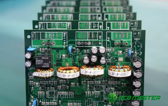
What Is Energy Stored in an Inductor?
An inductor is a passive electronic component that typically consists of a coil of wire wound around an air core or a magnetic core. When current flows through the coil, it generates a magnetic field around it. The energy associated with this magnetic field is the energy stored in the inductor.
Unlike a capacitor, which stores energy in an electric field, an inductor stores energy in a magnetic field. It also opposes changes in current through self-induced electromotive force, as described by Faraday's law of electromagnetic induction and Lenz's law.
The energy storage process has three key characteristics:
- Current increases: The magnetic field strengthens, and the inductor stores more energy.
- Current remains constant: Under ideal steady-state conditions, the magnetic field and stored energy remain constant.
- Current decreases: The magnetic field collapses, releasing energy back into the circuit or transferring it to another component.
This behavior makes inductors particularly important in circuits that require controlled energy transfer and current regulation.
What Is the Formula for Energy Stored in an Inductor?
The standard formula for the energy stored in an ideal inductor is:
E=(1/2)LI 2
Where:
- E = stored magnetic energy, measured in joules (J)
- L = inductance, measured in henries (H)
- I = instantaneous current through the inductor, measured in amperes (A)
The equation shows that stored energy is directly proportional to inductance and to the square of current.
For example, doubling the inductance doubles the stored energy at the same current. However, doubling the current increases the stored energy by a factor of four.
Example Calculation
Consider an inductor with an inductance of 100 µH carrying a current of 2 A.
Given:
L=100×10 −6 H
I=2 A
Substituting these values into the formula:
E=(1/2)×100×10 −6 ×2 2
E=200×10 −6 J
Therefore, the inductor stores 200 µJ (microjoules) of magnetic energy.
This calculation is useful when evaluating inductors for switching regulators, power management circuits, and other applications that rely on repeated energy storage and transfer.
How Does an Inductor Store and Release Energy?
The energy storage mechanism can be understood by examining how voltage, current, and magnetic flux interact.
For an ideal inductor with constant inductance, the voltage-current relationship is:
V=L(dI/dt)
This equation indicates that the voltage across an inductor is proportional to the rate of change of current.
When voltage is applied, current begins to change, creating a changing magnetic field. The power delivered to the inductor is:
P=VI
Substituting the inductor voltage relationship gives:
P=LI(dI/dt)
Since power represents the rate of change of energy, integrating this relationship from zero current to the final current produces the energy storage formula.
In practical circuits, the process occurs repeatedly. A switching controller regulates the charging and discharging intervals to deliver energy to a load while maintaining the required output voltage or current.
What Factors Affect Energy Stored in an Inductor?
Several electrical and physical characteristics influence an inductor's energy storage capability.
| Factor | Effect on Stored Energy | Engineering Consideration |
|---|---|---|
| Inductance | Higher inductance increases stored energy at a given current | Select an appropriate inductance for the operating frequency and topology |
| Current | Energy increases with the square of current | Check saturation current and RMS current ratings |
| Core material | Influences inductance, magnetic flux density, and saturation behavior | Choose a core suited to the frequency and power level |
| Core geometry and air gap | Affect magnetic energy capacity and saturation characteristics | Evaluate magnetic design requirements |
| Winding resistance | Causes conduction losses and heat generation | Consider DC resistance and thermal performance |
| Operating frequency | Influences core loss, AC winding loss, and practical efficiency | Select a component designed for the switching frequency |
Important distinction: Increasing inductance or current does not guarantee that a physical inductor can store more energy safely. Core saturation, winding temperature, insulation limits, and manufacturer specifications constrain its practical operating range.
Energy Stored in an Inductor vs. Energy Stored in a Capacitor
Inductors and capacitors are both energy-storage components, but they store energy through different physical mechanisms.
| Comparison | Inductor | Capacitor |
|---|---|---|
| Energy storage mechanism | Magnetic field | Electric field |
| Energy formula | E=(1/2)LI 2 | E=(1/2)CV 2 |
| Primary variable | Current | Voltage |
| Opposes | Changes in current | Changes in voltage |
| Common applications | Power conversion, filtering, energy transfer | Decoupling, filtering, voltage stabilization |
| Typical switching-converter role | Transfers energy between switching intervals | Smooths voltage and supports output energy storage |
In a DC-DC converter, inductors and capacitors often work together. The inductor controls current and transfers energy, while the capacitor helps maintain a stable output voltage and supplies transient load current.
Their coordinated operation is central to efficient power conversion.
Practical Applications of Inductor Energy Storage in PCB Design
Inductor energy storage is fundamental to numerous electronic systems. Its practical importance becomes especially clear in PCB design and PCBA manufacturing.
1. DC-DC Converters and Switching Power Supplies
Buck, boost, and buck-boost converters use inductors to store and transfer energy during switching cycles.
In a buck converter, the inductor stores energy when the switching element conducts and releases energy when the switching state changes. The resulting current supports a stable output when combined with appropriate output capacitance and control.
Engineers must evaluate inductance, saturation current, ripple current, DC resistance, and core losses to achieve the desired efficiency and thermal performance.
2. EMI Filtering and Noise Suppression
Inductors and chokes are widely used in electromagnetic interference (EMI) filters. Their impedance helps attenuate unwanted high-frequency currents, depending on the circuit configuration and frequency.
However, component selection alone does not guarantee effective noise suppression. PCB trace routing, grounding, return-current paths, switching-node area, and filter placement also influence EMI performance.
3. Automotive and Industrial Electronics
Automotive control modules, industrial power supplies, motor drives, and communication equipment often rely on inductors for energy conversion and current control.
These applications may impose demanding requirements for temperature range, vibration resistance, electrical transients, and long-term reliability. The selected inductor must meet the actual operating conditions rather than relying solely on its nominal inductance.
4. High-Density PCB and PCBA Assemblies
In compact electronic products, inductor placement and power-stage layout affect parasitic inductance, heat dissipation, and electromagnetic coupling.
For PCB designers, practical considerations include:
- Keeping high-current paths short and appropriately sized.
- Minimizing switching-loop area where possible.
- Providing adequate copper area for heat spreading.
- Maintaining suitable spacing between sensitive signal traces and noisy switching nodes.
- Verifying component height, footprint, soldering requirements, and assembly clearances.
These measures help improve circuit stability, manufacturability, and reliability.
Common Mistakes When Working with Inductor Energy Storage
Mistake 1: Ignoring the Square of Current
Because energy is proportional to I2I^2I2, a relatively small current increase can significantly increase the stored energy.
Engineers should evaluate peak current under startup, transient, overload, and fault conditions—not just nominal operating current.
Mistake 2: Selecting an Inductor Based Only on Inductance
Two inductors with the same nominal inductance may have very different saturation currents, DC resistance, core losses, and thermal characteristics.
A suitable selection process should consider the full electrical and mechanical specifications.
Mistake 3: Confusing Stored Energy with Power Loss
Stored magnetic energy is not the same as dissipated energy. An ideal inductor can store and return energy without dissipating it. Real inductors, however, exhibit winding resistance, core losses, and other parasitic effects that reduce efficiency.
Mistake 4: Overlooking PCB Layout
Poor layout can increase parasitic inductance, create excessive switching noise, and worsen thermal performance. These problems may persist even when the inductor itself is correctly specified.
How PCBMASTER Supports Reliable Power Electronics Manufacturing
For electronic products that depend on inductors and switching power circuits, PCB fabrication and PCBA assembly quality are important parts of overall system reliability.
PCBMASTER provides PCB manufacturing, component sourcing, SMT assembly, and PCBA services for a range of electronic applications. Its engineering support includes free manufacturing-file reviews to help identify potential fabrication and design issues before production.
The company reports an 80,000 m² factory, a team of more than 50 engineers, and quality management credentials including ISO 9001 and IATF 16949, alongside UL certification. These capabilities support projects ranging from rapid PCB prototyping to complex multilayer and high-density designs.
For power electronics projects, the engineering review process can help assess board-level considerations such as copper geometry, component footprints, thermal management, and manufacturing constraints. The inductor's electrical performance must still be validated against the circuit's actual operating conditions, including current ripple, peak current, switching frequency, and temperature.
PCBMASTER's integrated PCB and PCBA services can also help coordinate fabrication and assembly requirements, reducing the need to manage multiple manufacturing suppliers.
Conclusion: Why Understanding Inductor Energy Matters
The energy stored in an inductor is determined by its inductance and the square of the current flowing through it. This fundamental relationship explains how inductors support switching power conversion, current regulation, filtering, and energy transfer.
For practical engineering work, understanding the formula is only the starting point. Reliable designs also require appropriate component selection, saturation and loss analysis, thermal evaluation, and careful PCB layout.
By considering these factors during circuit design and manufacturing, engineers can improve power efficiency, control electromagnetic interference, and build more reliable electronic products.
Tags: #EnergyStoredInInductor #Inductor #PCBDesign #PCBA #SMT #PowerElectronics #DCDCConverter #PCBMASTER #ElectronicsEngineering
About the Author

Carol Luo
PCB Design EngineerI'm Carol, a PCB Engineer at PCBMASTER with experience in PCB design and manufacturing engineering since 2018. I focus on translating engineering requirements into reliable PCB solutions, with expertise in stack-up design, material selection, and design-for-manufacturing (DFM). I share practical engineering insights from real-world PCB design and production experience.
Visit Carol Luo's Profile

