








An Inductor Stores Energy in a Magnetic Field: Working Principle, Applications, and Design Considerations
An inductor stores energy in a magnetic field created when electric current flows through its coil. This fundamental electromagnetic principle makes inductors essential components in switching power supplies, DC-DC converters, filters, energy storage circuits, and electromagnetic systems. Understanding how inductors store and release energy helps engineers select suitable inductance values, core materials, current ratings, and PCB layouts for efficient, reliable electronic designs. For PCB and PCBA projects, proper inductor selection and circuit layout are critical to power efficiency, thermal performance, and electromagnetic compatibility.
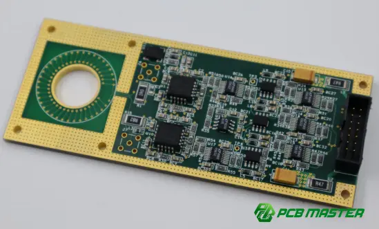
What Does an Inductor Store Energy In?
An inductor stores energy in its magnetic field, not directly in its wire or core material. When current flows through a coil, it generates a magnetic field around the conductor. As the current increases, the magnetic field strengthens and energy accumulates in that field.
An inductor typically consists of a coil of conductive wire, sometimes wound around a magnetic core made from ferrite, powdered iron, or another suitable material. The coil produces the magnetic field, while the core can concentrate the magnetic flux and increase inductance.
The energy stored in an ideal inductor is calculated using:
E=(1/2)LI 2
Where:
- E = stored energy in joules (J)
- L = inductance in henries (H)
- I = current through the inductor in amperes (A)
This equation shows that stored energy increases linearly with inductance but increases with the square of current. For example, doubling the current increases the stored energy by a factor of four, provided the inductor remains within its applicable operating limits.
How Does an Inductor Store and Release Energy?
The energy storage process follows the relationship between electric current and magnetic flux.
1. Energy Storage
When a voltage is applied across an inductor, current begins to change. The changing current produces a changing magnetic field, and energy is transferred from the electrical source into that field.
The inductor opposes changes in current through its self-induced electromotive force, described by:
V L =L(dI/dt)
For the passive sign convention, this equation indicates that the voltage across an ideal inductor is proportional to the rate of change of current.
2. Energy Retention
When current is maintained at a constant value in an ideal inductor, its magnetic field remains established and the stored energy remains constant. Unlike a capacitor, which stores energy in an electric field, an inductor stores energy in a magnetic field.
In a practical circuit, winding resistance, core losses, and other parasitic effects can dissipate energy as heat.
3. Energy Release
When the circuit requires the inductor to supply energy, the magnetic field collapses as current decreases. The inductor generates a voltage that opposes the current change, transferring energy back to the circuit or to another component.
This behavior is fundamental to switching converters, where inductors repeatedly store and release energy to regulate output voltage and current.
Inductor Energy Storage vs. Capacitor Energy Storage
Inductors and capacitors are both reactive components that store and release energy, but they operate through different physical mechanisms. Understanding this distinction helps engineers choose the right components for power conversion, filtering, and signal conditioning.
| Comparison | Inductor | Capacitor |
|---|---|---|
| Energy storage mechanism | Magnetic field | Electric field |
| Energy equation | \(E=\frac{1}{2}LI^2\) | \(E=\frac{1}{2}CV^2\) |
| Opposes changes in | Current | Voltage |
| Main electrical property | Inductance (H) | Capacitance (F) |
| Typical applications | DC-DC converters, chokes, LC filters | Decoupling, voltage smoothing, timing circuits |
| Ideal DC steady-state behavior | Acts as a short circuit | Acts as an open circuit |
Key takeaway: An inductor resists rapid changes in current, whereas a capacitor resists rapid changes in voltage. Combining the two allows engineers to design filters, resonant circuits, and efficient power conversion systems.
What Factors Affect the Energy an Inductor Can Store?
Although the ideal energy equation is straightforward, the actual energy storage capability of an inductor depends on several electrical, magnetic, and thermal factors.
1. Inductance Value
Inductance directly determines the amount of energy stored at a given current. Higher inductance generally allows more energy storage at the same current, according to E=(1/2)LI 2 .
However, a higher inductance value does not automatically make an inductor suitable for every application. Engineers must also consider operating frequency, current ripple, winding resistance, physical size, and saturation behavior.
2. Magnetic Core Material
The core material influences inductance, magnetic flux density, core losses, and saturation characteristics.
- Ferrite: Commonly used in high-frequency switching power supplies because of its relatively low core losses at suitable operating frequencies.
- Powdered iron: Often used in power inductors because distributed air gaps can provide useful energy storage and gradual saturation characteristics.
- Air core: Avoids magnetic core saturation and can offer low core losses, making it useful in certain RF and high-frequency applications.
Core selection must match the operating frequency, current, temperature, and required inductance.
3. Saturation Current
Magnetic core saturation is one of the most important limitations in practical inductors. As current increases, the core approaches its magnetic saturation region, where incremental inductance can decrease significantly.
When inductance drops, current ripple may increase, potentially causing excessive current, overheating, or failure of the switching circuit.
Engineers should evaluate the manufacturer's specified saturation current and temperature-dependent performance rather than relying on nominal inductance alone.
4. Winding Resistance and Thermal Performance
An inductor's winding resistance generates copper loss:
P copper =I RMS 2 R
Core losses also contribute to heat generation, particularly in switching applications. Excessive temperature can reduce efficiency and affect component reliability.
PCB copper geometry, thermal pathways, airflow, and nearby heat-producing components all influence the inductor's operating temperature.
Where Is Inductor Energy Storage Used?
Inductors store and release energy in many electronic systems. Their role depends on the circuit topology and operating conditions.
Switching Power Supplies and DC-DC Converters
In buck and boost converters, the inductor temporarily stores energy during part of the switching cycle and transfers energy during another part. This process helps convert one DC voltage level to another while controlling current ripple.
For example, in a buck converter, the inductor stores energy when the switching transistor conducts and continues supplying current to the load when the transistor turns off. The exact current paths depend on the converter topology.
LC Filters
Inductors and capacitors work together to attenuate unwanted frequency components. The inductor's opposition to changing current and the capacitor's response to changing voltage help shape the circuit's frequency response.
Applications include power supply filtering, conducted-noise suppression, and signal conditioning.
Electromagnetic Systems
Inductors also store magnetic energy in relays, solenoids, transformers, and other electromagnetic devices. Their magnetic fields support energy transfer, actuation, or coupling, depending on the design.
However, a transformer is not simply an energy-storage inductor: its primary purpose is usually to transfer energy between windings through magnetic coupling.
How PCB Design Affects Inductor Performance
Selecting the right inductor is only part of a reliable electronic design. PCB layout and assembly decisions can also influence electrical efficiency, electromagnetic interference (EMI) , and thermal performance.
1. Minimize High-Current Loop Area
In switching power supplies, the input switching loop and other high-di/dt current paths can generate substantial electromagnetic noise. Keep critical loops compact and place the inductor close to the relevant switching and output components, following the converter manufacturer's layout recommendations.
2. Consider Copper Width and Current Capacity
The PCB traces and copper planes connected to the inductor must accommodate the expected RMS and peak currents. Insufficient copper capacity can increase resistance, voltage drop, and temperature rise.
Trace width calculations should account for copper thickness, allowable temperature rise, ambient conditions, and the applicable design standards.
3. Evaluate Thermal Management
An inductor operating near its current or temperature limits can affect adjacent components and PCB materials. Appropriate component spacing, copper distribution, and thermal assessment help maintain reliable operation.
4. Control EMI and Magnetic Coupling
Magnetic fields can couple into nearby circuits, particularly sensitive analog or RF sections. Component placement, return-current paths, shielding requirements, and the orientation of magnetic components should be considered during layout.
PCBMASTER supports PCB fabrication and PCBA assembly for power electronics and other electronic applications. Its engineering file review service can help identify manufacturability and layout concerns before production, although electrical performance and EMI validation still require application-specific engineering analysis and testing.
Common Mistakes When Designing Inductor-Based Circuits
| Common mistake | Potential consequence | Recommended approach |
|---|---|---|
| Selecting an inductor based only on inductance | Saturation or excessive losses | Verify saturation current, RMS current, and core losses |
| Ignoring winding resistance | Excessive heat and reduced efficiency | Evaluate DC resistance and temperature rise |
| Using an unsuitable core material | High-frequency losses or premature saturation | Match core properties to frequency and current |
| Placing switching components too far apart | Increased parasitic inductance and EMI | Optimize critical current loops |
| Ignoring component tolerances | Unexpected ripple or converter behavior | Check inductance tolerance and operating conditions |
| Overlooking thermal conditions | Reduced reliability | Validate performance under worst-case operating conditions |
PCBMASTER's Approach to Reliable PCB and PCBA Manufacturing
Reliable inductor-based circuits require more than selecting an appropriate magnetic component. PCB fabrication quality, assembly accuracy, copper design, and production inspection all contribute to the performance of the finished electronic product.
PCBMASTER provides PCB, PCBA, and SMT services for a wide range of electronics applications, including power electronics, industrial control, and communications.
Its relevant capabilities include:
- Engineering file review: Free review of manufacturing files to identify potential fabrication and design issues.
- PCB and PCBA integration: PCB manufacturing and assembly services to support projects from prototype development to production.
- Quality management: ISO 9001 and IATF 16949 quality management certifications, along with UL certification and RoHS-related compliance offerings.
- Manufacturing and inspection: Production processes and inspection procedures designed to support consistent product quality.
For inductor-based power circuits, engineers should provide complete design documentation and specify relevant requirements, including copper thickness, board stack-up, operating current, thermal conditions, and assembly constraints. These details help align PCB manufacturing with the circuit's electrical and mechanical requirements.
Conclusion
An inductor stores energy in a magnetic field created by current flowing through its coil. Its ideal stored energy is proportional to inductance and the square of current, expressed as E=(1/2)LI 2 .
This principle underpins switching regulators, DC-DC converters, LC filters, and many electromagnetic systems. To achieve reliable performance, engineers must evaluate inductance, saturation current, core losses, winding resistance, thermal behavior, and PCB layout together.
For production-ready electronic designs, combining appropriate component selection with sound PCB engineering, manufacturing controls, and validation testing helps deliver efficient and reliable circuit performance.
Tags: #Inductor #MagneticField #EnergyStorage #PowerElectronics #DCDCConverter #PCBDesign #PCBA #SMT #PCBMASTER #ElectronicsEngineering
About the Author

Carol Luo
PCB Design EngineerI'm Carol, a PCB Engineer at PCBMASTER with experience in PCB design and manufacturing engineering since 2018. I focus on translating engineering requirements into reliable PCB solutions, with expertise in stack-up design, material selection, and design-for-manufacturing (DFM). I share practical engineering insights from real-world PCB design and production experience.
Visit Carol Luo's Profile