








Pot Variable Resistor: What It Is, How It Works, Types & Applications
One of the most common adjustable components used in modern electronics is a pot variable resistor, which is used to adjust everything from speaker volume to fine tuning electronic circuits. It is indispensable in all sorts of devices . From consumer products to industrial equipment . The ability to adjust resistance with a simple mechanical adjustment .
Term is often used interchangeably with potentiometer, but many people don’t really know how a pot variable resistor works, which type is best for a specific application or how to select the right one for a circuit. Knowing these basics will help you make better design decisions and avoid common selection mistakes.
This guide covers what a pot variable resistor is, how it works, the main specifications, the major types, common uses, and things to consider when selecting one for your project. Whether you are an electronics novice, a PCB designer or an engineer, you will get a clear understanding of this versatile component and its role in electronic systems.
What Is a Pot Variable Resistor?
A pot variable resistor is an electronic device that changes resistance by moving a contact called a wiper. It is often used to control voltage, current or signal levels in an electronic circuit.
Potentiometer variable resistors have a resistance that can be changed by the user, unlike a fixed resistor. You flip a switch or turn a knob and the wiper moves along a resistive track, varying the resistance value. Its uncomplicated design makes it useful for applications such as volume controls, light dimmers, sensor calibration and PCB circuits.
Definition and basic function
A pot variable resistor’s principal use is to vary the resistance and so to control electrical signals. Depending upon the connection it can be used to divide voltage or limit current.
Basic functions are :
- Adjusting output voltage in a circuit
- Controlling current flow
- Fine-tuning electronic equipment
- Calibrating sensors and measuring devices
For example , when you turn the knob on a speaker to change the volume , you are changing the volume by using a variable resistor . This is called a pot . Turning the knob changes the resistance, letting more or less of the audio signal pass through the circuit.
The pot variable resistor is simple, low cost and reliable. It has wide range of applications in consumer electronics, industrial equipment, automotive systems and PCB designs.
Main components
The variable resistor pot is easy to build, but it has a few important parts. Each part plays an important part in the fine and accurate control of the resistance.
| Component | Function |
|---|---|
| Resistive track | Provides the fixed resistance path that the wiper moves across. |
| Wiper | A movable contact that slides along the resistive track to change the resistance. |
| Three terminals | Two connect to the ends of the resistive track, while the center terminal connects to the wiper. |
| Shaft or slider | Allows the user to rotate or slide the wiper manually. |
| Housing | Protects the internal components from dust and mechanical damage. |
For instance, in a rotary potentiometer the shaft is turned, and the wiper moves along a circular resistive track. The wiper of a slide potentiometer moves in a straight line as the slider is displaced. The forms may be different but the principle is the same.
Pot variable resistor vs. Potentiometer
It’s no big deal – for the most part. Potentiometers are also known as pot variable resistors. This is especially the case where the component is used for manual adjustment of resistance.
Pot is short for potentiometer and the two words are often interchangeable in electronics . The exact meaning depends on the use of the component in a circuit. When the three terminals are joined together it acts as a voltage dividing potentiometer. However , with only 2 terminals it is the same component that is a variable resistor ( aka rheostat ) controlling the current .
| Feature | Pot Variable Resistor | Potentiometer |
|---|---|---|
| Basic meaning | Adjustable resistor | Adjustable resistor |
| Common name | Pot, variable resistor | Potentiometer, pot |
| Number of terminals | Usually 3 (can use 2) | 3 |
| Main function | Adjust resistance or current | Divide voltage |
| Typical use | Current adjustment, tuning | Volume control, signal adjustment |
Pot, variable resistor and potentiometer all refer to the same component in everyday electronics. For the engineer and hobbyist. The difference is usually in how you hook up and use the device and not the type of part.

What Are the Key Specifications of a Pot Variable Resistor?
The most important parameters of a pot variable resistor are resistance value , power rating , taper , tolerance and operating life . These parameters determine how well the component will perform and whether it is suitable for a particular electronic application.
Armed with these specifications, you’ll be able to select the proper pot variable resistor for your circuit. Incorrect value or rating can lead to poor performance, improper adjustment or even component failure.
Resistance value
The resistance value is the maximum resistance between the two outer terminals of a pot variable resistor, in ohms (Ω) .
They are typically in the range of 100 Ω to 1 MΩ or more, depending on the application. Common values are 1 kΩ, 5 kΩ, 10 kΩ, 50 kΩ and 100 kΩ.
The total resistance remains constant , but the resistance from the center terminal to either of the outer terminals changes gradually as the wiper is moved .
General Selection Criteria:
- 1 kΩ–10 kΩ: Higher current circuits and LED controls
- 10 kΩ–100 kΩ: Audio equipment and analog signal circuits
- 100 kΩ–1 MΩ: High-impedance sensor and measurement circuits
The 10 kΩ potentiometer is often used as a volume control, as it can be used to smoothly adjust the signal without too much load on the audio circuit.
Power rating
The power rating is the maximum electrical power a pot variable resistor can safely dissipate without damage or overheating.
The power rating is in watt (W) . Typical ratings are 0.1 W, 0.25 W, 0.5 W, 1 W and 2 W.
If the resistor is required to dissipate more than its rated power, the excess heat may damage the resistive track and reduce the life of the component.
When choosing a power rating, you want to consider:
- Operating voltage
- Expected current
- Ambient temperature
- Safety margin
A good practice is to use a potentiometer with a power rating higher than the power dissipation expected in the circuit.
A small PCB adjustment circuit might only need a 0.25 W potentiometer while an industrial controller that handles a higher current could need a 1 W or 2 W unit.
Taper (linear vs. logarithmic)
Taper is a description of how the resistance varies as the shaft or slider is moved.
There are two common types of tapers:
| Taper | Resistance Change | Typical Applications |
|---|---|---|
| Linear taper | Resistance changes evenly across the full rotation. | Sensor adjustment, voltage control, industrial electronics |
| Logarithmic (audio) taper | Resistance changes slowly at first and more rapidly near the end of the rotation. | Volume controls and audio equipment |
The letter B is used in many places to identify linear taper. The letter A is normally used for logarithmic taper. But, letter codes can vary from manufacturer to manufacturer, so always check the datasheet before selecting a component.
Example: A speaker volume control is usually a logarithmic potentiometer because the human ear perceives changes in sound level on a logarithmic scale. In comparison, an adjustable power supply typically uses a linear potentiometer for more reliable voltage adjustment.
Tolerance and operating life
To summarise, tolerance indicates how close the actual resistance is to the nominal value, and operating life indicates how many adjustment cycles the pot variable resistor can undergo before its performance deteriorates.
Typical resistance tolerances are .
- ±20% (common for general-purpose carbon potentiometers)
- ±10%
- ±5% (higher-precision models)
For example, a 10 kΩ potentiometer with a tolerance of ±10% may actually be as low as 9 kΩ or as high as 11 kΩ in resistance.
The operating life is usually expressed in terms of rotational or sliding cycles. General purpose potentiometers are usually rated for 10,000 to 50,000 cycles while high quality conductive plastic models can last beyond 1 million cycles.
For precision circuits, choose a pot variable resistor with tighter tolerance and for applications which require frequent adjustment (such as industrial control panels or laboratory equipment) choose one with longer operating life.
How Does a Pot Variable Resistor Work?
A pot variable resistor works by sliding a wiper across a resistive track , changing the resistance between its terminals . It can be used for controlling voltage and current or signal levels in an electronic circuit.
Pot, or potentiometer, variable resistors are adjusted by hand, either with a shaft or a slider. Fixed resistors are not adjustable. The electrical path changes as the wiper moves, and thus the operation of the circuit can be precisely controlled. This simple operating principle makes potentiometers one of the most widely used adjustable electronic components.
Operating principle
A pot variable resistor varies electrical resistance by moving a conductive wiper along a fixed resistive track.
The element contains a resistive element of constant overall resistance. This track is supported by a movable wiper and is divided into two parts. Moving the shaft or slider moves the wiper, and changes the resistance between the centre terminal and each of the outer terminals.
The total resistance between the two outer terminals remains unchanged. Instead the two sides of the wiper are varied in reciprocal resistances. One side gets bigger and the other smaller by the same amount.
Say ruler 100cm long. If you slide a marker from one end of the ruler to the other, the length on either side changes. But the total length of the ruler is always 100 cm. A pot variable resistor works the same way too.
How the wiper adjusts resistance
By moving the contact point on the resistive track, the wiper changes resistance.
As the wiper moves , it varies the amount of resistive material the electricity has to travel through . Longer electrical path = higher resistance Shorter electrical path = lower resistance
This is how the adjustment process works:
- The user rotates the shaft or moves the slider.
- The wiper moves to a new position on the resistive track.
- The resistance between the center terminal and each outer terminal changes.
- The circuit responds by adjusting voltage, current, or signal level.
When you turn the volume knob on a radio, the wiper moves in a gradual fashion. It changes the level of the audio signal and makes the sound louder or quieter instead of suddenly turning it on or off.
Voltage divider and variable resistor modes
A pot variable resistor can be used as a voltage divider or a variable resistor depending upon how you wire it .
The operating modes are:
| Mode | Connection | Primary Function | Common Applications |
|---|---|---|---|
| Voltage divider | Uses all three terminals | Produces an adjustable output voltage | Volume controls, sensor circuits, analog inputs |
| Variable resistor (rheostat) | Uses the wiper and one outer terminal | Adjusts current by changing resistance | LED dimming, motor speed adjustment, circuit tuning |
In voltage divider operation the input voltage is applied across the two outer terminals and the adjustable output is taken from the center terminal . As the wiper moves, the output voltage varies smoothly.
In variable resistor mode only two of the terminals are connected. The wiper just adds or subtracts resistance in series to the circuit allowing one to control the current.
For instance, a microphone volume control typically takes advantage of the voltage divider configuration, while a basic LED brightness adjustment circuit might employ the same component as a variable resistor. Both applications use the same adjustable resistive element, but wired differently.
What Are the Main Types of Pot Variable Resistors?
There are 4 major types of pot variable resistors. Potentiometers Rotary Potentiometers Slide Potentiometers Trimmer Potentiometers Digital Potentiometers. Each type controls resistance in its own way and is designed for specific purposes.
The best solution depends on the way the resistance is adjusted, how often it is used and whether it is adjusted manually or electronically.
Rotary potentiometers
Rotary potentiometers are potentiometers that use a shaft to control resistance.
The most common of the pot variable resistors are. The inside of the component has a circular resistive track and a wiper is swept across it as the shaft is turned, giving a smooth continuous adjustment of resistance.
The rotary potentiometer is popular because it is easy to use, reliable, and comes in a variety of resistance values and taper types.
Typical applications are the following:
- Audio volume and tone controls
- Power supply adjustment
- Instrument panels
- Consumer electronics
- Industrial control equipment
A rotary pot is what you usually see on a home stereo or guitar amp as a volume knob. When you turn the knob the volume goes up or down smoothly .
Slide potentiometers
Slide potentiometers vary resistance by sliding a slider back and forth.
The wiper does not rotate but moves along a linear resistive element . The slider's position is displayed, so users can see what the setting is without changing anything.
Slide potentiometers allow precise manual control and are frequently used where it is important to see the level of adjustment.
Common applications include:
- Audio mixing consoles
- Graphic equalizers
- Lighting control systems
- Laboratory equipment
On an audio mixing board, the engineers can adjust the volume of each channel separately using the sliders, and the settings are all visible at a glance.
Trimmer potentiometers
A trimmer potentiometer ( trimpot ) is a small variable resistor meant to be adjusted occasionally to calibrate something, not to be manually adjusted often.
Trimmer potentiometers are usually soldered right to a PCB and adjusted with a screwdriver. Once they are calibrated they rarely move again.
Trimpots are smaller and cheaper than standard potentiometers, and are therefore more suitable for internal circuit adjustments.
Typical applications are:
- PCB calibration
- Sensor adjustment
- Voltage reference tuning
- Factory equipment setup
- Test and measurement instruments
Example: An engineer may use a trimmer potentiometer to set the output voltage of a circuit during manufacturing prior to shipping the product.
Digital potentiometers
A digital potentiometer electronically changes resistance , rather than with a mechanical knob or slider .
Instead of physically sliding a wiper, a digital potentiometer uses integrated circuits to change resistance in small electronic steps. The adjustment is controlled by a microcontroller, which has interfaces like I 2 C or SPI.
Digital potentiometers provide greater repeatability, remote control and simple integration into automated systems without the need for manual adjustments.
Typical uses include:
- Microcontroller projects
- Smart devices
- Industrial automation
- Programmable power supplies
- IoT and embedded systems
A digital potentiometer could be used to automatically adjust the audio level in a smart speaker so the user doesn’t have to turn a physical knob.
Comparison Table
| Type | Adjustment Method | Best For | Typical Applications |
|---|---|---|---|
| Rotary potentiometer | Rotating a shaft | Frequent manual adjustment | Volume controls, power supplies, industrial panels |
| Slide potentiometer | Sliding a lever | Visual position control | Audio mixers, equalizers, lighting systems |
| Trimmer potentiometer | Turning a small screw | Circuit calibration | PCB tuning, sensor calibration, factory adjustment |
| Digital potentiometer | Electronic control (I²C/SPI) | Programmable adjustment | Embedded systems, IoT devices, automated equipment |
All pot variable resistors do basically the same thing, they vary resistance but they vary how you vary it, how accurate the control is, and what you use them for. Rotary and slide potentiometers are good for frequent user interaction . Trimmer potentiometers are ideal for single calibration. Digital potentiometers are most suitable for electronically controlled systems.
How Does a Pot Variable Resistor Compare with Similar Components?
A pot variable resistor shares some things in common with fixed resistors, rheostats and digital potentiometers, but each part is designed for a different purpose. Knowing the differences helps you select the right component for your circuit.
Pot variable resistor vs. fixed resistor
A pot is a variable resistor and the resistance can be varied . A fixed resistor has a constant resistance value which cannot be altered.
The resistance of a fixed resistor is constant once it is manufactured. It is used for current limiting , voltage division , and electronic component protection . Conversely, a pot variable resistor allows the user to change the resistance by turning a nob or sliding a slider.
| Feature | Pot Variable Resistor | Fixed Resistor |
|---|---|---|
| Resistance | Adjustable | Fixed |
| Adjustment | Manual | Not adjustable |
| Typical terminals | 3 (or 2 when used as a variable resistor) | 2 |
| Main purpose | Adjustable control | Stable circuit operation |
| Common applications | Volume controls, calibration, dimmers | Current limiting, pull-up resistors, voltage dividers |
Example: A LED circuit may have a fixed resistor to provide a constant current for normal operation. If you want to make the brightness adjustable you can add a pot variable resistor and the user can manually adjust the current.
Pot variable resistor vs. Rheostat
A rheostat is a resistor with a variable resistance used primarily to control current. A pot variable resistor is a 3 terminal component which can be used as a potentiometer or rheostat.
Many potentiometers may be used as rheostats by using only the wiper and one outer terminal. But conventional rheostats are usually rated for higher current and higher power than common potentiometers.
| Feature | Pot Variable Resistor | Rheostat |
|---|---|---|
| Number of terminals | 3 (typically) | Usually 2 in use |
| Primary function | Adjust voltage or resistance | Control current |
| Power handling | Low to moderate | Moderate to high |
| Typical applications | Audio circuits, sensors, PCB electronics | Motor control, heaters, power circuits |
For example a 10 kΩ pot is good for adjusting an audio signal. But a wire wound rheostat is more suitable for controlling the current in a high power motor or heating element.
Pot variable resistor vs. digital potentiometer
Manually adjust a pot-variable resistor, electronically adjust resistance with a digital pot, using a microcontroller or other processor.
In a conventional pot variable resistor a mechanical wiper moves as the user turns a shaft or moves a lever. A digital potentiometer is just a digital potentiometer. electronic discrete steps resistance changes. It has an integrated circuit in it. I²C or SPI . You can talk to it.
| Feature | Pot Variable Resistor | Digital Potentiometer |
|---|---|---|
| Adjustment | Manual | Electronic |
| Moving parts | Yes | No mechanical adjustment |
| Control method | Knob or slider | Microcontroller or processor |
| Precision | Depends on mechanical position | High repeatability with fixed steps |
| Typical applications | Consumer electronics, industrial controls | Embedded systems, IoT devices, programmable equipment |
Example: A home stereo typically includes a manual volume control potentiometer. A digital potentiometer may be used in a smart speaker or a programmable amp, so the system can automatically change the volume in software.
What Are the Common Applications of Pot Variable Resistors?
Potentiometers are used to tune electrical signals, change output settings, and calibrate electronic circuits. Typical applications are audio volume control, LED brightness control, industrial control equipment and PCB circuit tuning.
Pot variable resistors are handy any time you want to have a circuit that can be controlled manually or by program instead of being fixed . Pot variable resistors provide a smooth and adjustable resistance .
Audio volume control
Potentiometer resistors are often used in audio equipment to control sound volume by controlling the strength of an audio signal.
In a typical audio circuit, a potentiometer serves as a voltage divider. When the user turns the volume knob the position of the wiper changes , decreasing or increasing the signal level sent to the amplifier .
Typical applications include:
- Speakers
- Headphones
- Amplifiers
- Radios
- Musical instruments
Audio equipment uses a logarithmic taper potentiometer, because human ears do not respond linearly to changes in sound. The taper provides a smoother and more natural feel to the volume control.
For instance, if the user turns up the volume knob on a speaker slowly, the sound will increase gradually instead of being loud all of a sudden. This fine control is made possible by the pot, or variable resistor.
LED brightness adjustment
A pot variable resistor can vary LED brightness by varying the current through the LED.
When connected in a proper LED control circuit, the potentiometer changes resistance and hence the current level . If the resistance is lower, more current will flow, and the LED will be brighter. If the resistance is higher, the current will be lower, and the LED will be dimmer.
Typical applications are:
- LED lamps
- Display panels
- Indicator lights
- DIY electronics projects
Example: A user can turn a control knob of an adjustable LED desk lamp to change the brightness level. The variable resistor in the pot offers a simple and inexpensive means of adjustment.
In high power LED systems, a potentiometer is often used as a control input to a driver circuit, rather than directly controlling the LED current.
Industrial control equipment
Pot Variable Resistors are used in industrial equipment to give manual adjustment and fine control of machine parameters.
The operators of many industrial systems have to tune the settings, e.g. speed, position or level of output. A potentiometer offers an easy interface between the operator and the electronic control system.
Applications include, but are not limited to:
- Motor speed controllers
- Machine control panels
- Test equipment
- Temperature controllers
- Calibration devices
Engineers generally select potentiometers for industrial use that are more rugged, more precise and have a longer operational lifetime to withstand frequent use.
A pot variable resistor may be connected to a control knob on a machine in a factory. The operator can change the resistance value to change the machine speed . This will change the control signal sent to the motor controller .
PCB and electronic circuit design
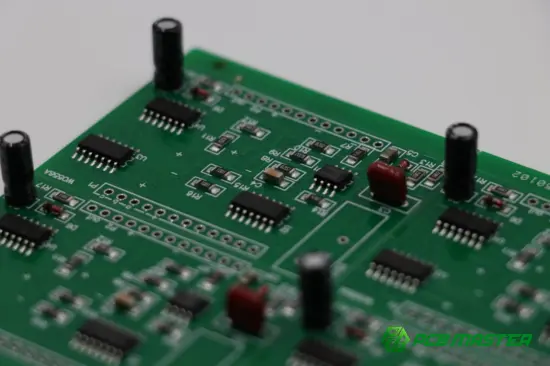
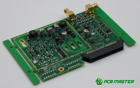
Pot variable resistors are often used in PCB designs for circuit adjustment, testing and calibration.
Engineers often use potentiometers to tune the performance of a circuit without physically changing components during the development and manufacture of printed circuit boards (PCBs). They are especially useful when the actual values have to be fine-tuned after assembly.
Typical PCB applications are:
- Sensor calibration
- Voltage adjustment
- Signal tuning
- Amplifier gain control
- Prototype development
You'll often see small trimmer potentiometers on PCBs because they are small and can be finely tuned with a screwdriver.
It may be necessary to do a small voltage correction on a sensor circuit after production. The engineers can simply tweak a trimmer potentiometer to get the proper output value instead of having to redesign the PCB .
As a simple method to tweak and fine-tune circuit performance, pot variable resistors continue to be a key part in PCB and electronic circuit design.
How Do You Choose the Right Pot Variable Resistor?
Choose the pot variable resistor according to the resistance value, taper type, power rating and mounting style you need. The correct choice will ensure stable operation, precise tuning and longer service life of components.
Before choosing a potentiometer, you must know: the application of the potentiometer, the power it must handle and how it will be mounted in the final product.
Selecting the resistance value
The resistance value determines the range of adjustment of a pot variable resistor . It should be matched to what the circuit requires .
Resistance is measured in ohms (Ω). This is the resistance between the two outer terminals at maximum. Common Potentiometer Variable Resistors: Values: 1kΩ, 5kΩ, 10kΩ, 50kΩ, 100kΩ.
If the resistance value is higher, it will decrease the flow of current and if the resistance value is lower, then more current will flow through. The correct value depends on the circuit design, and the range of adjustment needed.
Examples of general selection:
- 1 kΩ–10 kΩ: Suitable for current control and low-impedance circuits
- 10 kΩ–100 kΩ: Common for audio controls and analog circuits
- 100 kΩ or higher: Used in high-impedance sensor and measurement circuits
The reason why a 10 kΩ potentiometer is used for audio volume controls is it allows the signal to be controlled continuously, and it does not affect the amplifier circuit much.
Choosing the taper
Taper is the change in resistance as the shaft or slider moves .
Linear taper and log taper are two of the most common types.
| Taper Type | Resistance Change | Common Uses |
|---|---|---|
| Linear taper | Changes evenly throughout the adjustment range | Voltage adjustment, sensors, test equipment |
| Logarithmic taper | Changes slowly at first and faster later | Audio volume controls |
The linear potentiometer provides predictable adjustment, and is therefore a good choice for applications where the output must vary proportionally.
For audio applications , a logarithmic potentiometer is preferred . Human hearing is logarithmic in nature . It provides the user with a way to feel that the volume changes are smooth and natural.
A speaker's volume control has a logarithmic taper, while the calibration control of a circuit has a linear taper.
Matching the power rating
The wattage rating tells you how much electrical power a pot variable resistor can safely dissipate without burning up.
Power rating is Watt (W). If the pot is subjected to more power than its rating, the resistive track can be damaged or it can fail.
Remember when selecting a power rating:
- Circuit voltage
- Current flowing through the component
- Operating temperature
- Safety margin
Usually a 0.25W or 0.5W potentiometer is sufficient for low power PCB adjustment. If you require higher currents you may have to use a higher power model or a wirewound potentiometer .
For example a small sensor calibration circuit would typically use a low power trimmer potentiometer, whereas a motor control application would need a more rugged high power variable resistor.
Selecting the mounting type
Mounting type is how the pot variable resistor is mounted and wired inside the device.
They are normally mounted in the following ways:
| Mounting Type | Description | Typical Applications |
|---|---|---|
| Through-hole | Pins inserted through PCB holes and soldered | Traditional PCB assemblies |
| Surface-mount (SMD) | Mounted directly on the PCB surface | Compact electronic devices |
| Panel mount | Installed through an enclosure or control panel | User-operated equipment |
Select the mounting style based on the PCB layout, available space and adjustment of the component.
For example, a small electronic device may use an SMD trimmer potentiometer to save PCB space, while an industrial control panel may use a panel mount rotary potentiometer for easy user access.
The right mounting style will improve the reliability, assembly speed and performance of your product.
Conclusion
This article explains the features, working principle, types and applications of a Potentiometer, so that engineers and hobbyists of electronics can choose the right components for different circuit requirements. From audio level control to LED brightness to PCB design, this humble part remains a key element of modern electronics.
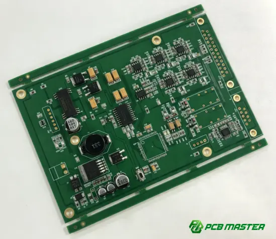
As electronic products become smaller and more reliable, component selection is important for stable performance and easy manufacturing. PCBMASTER has experience in PCB and PCBA solutions and can offer professional support for electronic projects, helping our customers to optimise component selection and to ensure reliable circuit designs.
When you are designing a prototype or preparing for mass production, the right knowledge of components like pot variable resistors can improve the accuracy of your design, reduce potential problems and help lead to better product quality.
FAQs
Can a pot variable resistor be used as a rheostat?
A pot variable resistor can be used as a rheostat with only 2 terminals of the 3 .
All three pins are utilised and a potentiometer is typically a voltage divider. But if the wiper terminal is connected to one of the outer terminals it will then act as a variable resistor (rheostat) to control the current flow .
Such a setup is common in applications like LED brightness control, motor speed control and circuit tuning. But a dedicated rheostat may be better for high power applications, as they are designed for handling more current and heat.
What resistance value is best for a pot variable resistor?
The optimum value of resistance is determined by the circuit requirements and the amount of adjustment required.
Common values for pot variable resistors are 1k, 10k, 50k and 100k. Low values are used for high current circuits and high values for low current signal circuits.
For instance:
- 10 kΩ potentiometers are commonly used for audio volume controls.
- 50 kΩ–100 kΩ potentiometers are often used in sensor and signal adjustment circuits.
- 1 kΩ–5 kΩ potentiometers may be used for voltage or current adjustment applications.
Always check the requirements of the circuit before selecting a resistance value.
What is the difference between linear and logarithmic taper?
The difference is in how the resistance changes as you move the knob / slider.
A linear taper potentiometer is a potentiometer where the resistance changes linearly with the adjustment range. For example, half turning the shaft produces about half the total resistance . It finds extensive use in voltage adjustment, sensors and calibration circuits.
The resistance of a Logarithmic Taper potentiometer does not change linearly. It changes a little at the beginning, and a lot at the end. This is mainly used for audio applications as the human ear is responsive in a logarithmic manner.
Logarithmic taper potentiometers are used for volume controls on speakers and amplifiers. These are to allow for a more gradual transition in listening.
How do you test a pot variable resistor with a multimeter?
To test a pot variable resistor with a multimeter you can measure the resistance changes between the terminals.
Make the following changes:
- Turn off the power and disconnect the potentiometer from the circuit.
- Set the multimeter to the resistance (Ω) mode.
- Measure the resistance between the two outer terminals to check the total resistance value.
- Connect one probe to the wiper terminal and the other probe to an outer terminal.
- Slowly rotate the shaft or move the slider.
- Check whether the resistance changes smoothly.
A good potentiometer will change resistance smoothly and evenly. If the resistance is jumping, infinite or unsteady, it may indicate that the part is worn or damaged.
About the Author

Carol Luo
PCB Design EngineerI'm Carol, a PCB Engineer at PCBMASTER with experience in PCB design and manufacturing engineering since 2018. I focus on translating engineering requirements into reliable PCB solutions, with expertise in stack-up design, material selection, and design-for-manufacturing (DFM). I share practical engineering insights from real-world PCB design and production experience.
Visit Carol Luo's Profile

