








Common Resistor Values: Standard E-Series Chart, Color Codes, and Selection Guide
The common resistor values in the E-series system are standardized, which is useful for the engineer in selecting practical resistance values to be used in electrical circuit design and PCB production. Knowledge of the E12, E24, E96 and E192 resistor series, resistor color codes, tolerances and application requirements is important for reliable circuit performance. PCBMASTER is a professional PCB and PCBA manufacturer , with strong quality control systems such as ISO 9001, IATF 16949 and UL certification requirements, providing high quality PCB assemblies and accurate component integration for a wide range of electronic applications.
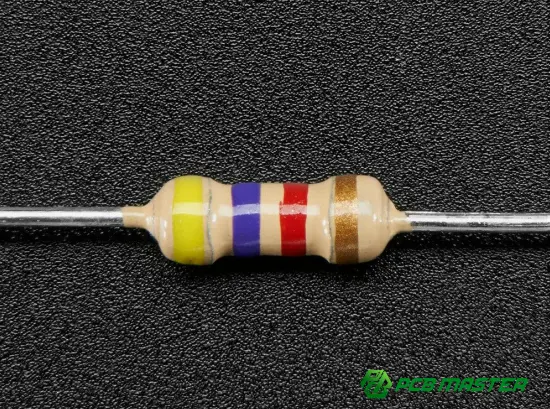
What Are Common Resistor Values and Why Are They Standardized?
Resistors are one of the most common passive components in electrical circuits. They manage current , split voltages , establish biasing conditions , protect delicate components , and regulate signal levels throughout everything from consumer electronics to automobile systems .
But manufacturers cannot generate every potential resistance value. To facilitate production, inventory management, and circuit design, resistor values are grouped into standardized preferred number series (E-series values) .
The E-series system is described in the international standards . The tolerance requirements determine the intervals of each decade of resistance. Engineers do not just use any figure between 10Ω and 100Ω, they choose from a list of conventional values.
Typical resistor series include:
| E-Series | Number of Values per Decade | Typical Tolerance | Common Applications |
|---|---|---|---|
| E6 | 6 | ±20% | General-purpose, low-precision circuits |
| E12 | 12 | ±10% | Consumer electronics and basic circuits |
| E24 | 24 | ±5% | Most standard PCB designs |
| E48 | 48 | ±2% | Precision applications |
| E96 | 96 | ±1% | Industrial and automotive electronics |
| E192 | 192 | ±0.5% or better | High-precision circuits |
Key point: The more stringent the resistor tolerance requirement , the greater the availability of standard values .
Standard resistor values simplify procurement, reduce production cycle time and increase cost efficiency for PCB designers and manufacturers.
Standard E-Series Resistor Value Chart
E12 Resistor Values (±10% Tolerance)
The E12 series is commonly used when moderate accuracy is sufficient.
| Base Values per Decade |
|---|
| 10, 12, 15, 18, 22, 27, 33, 39, 47, 56, 68, 82 |
Examples:
- 10Ω, 12Ω, 15Ω, 18Ω...
- 100Ω, 120Ω, 150Ω, 180Ω...
- 1kΩ, 1.2kΩ, 1.5kΩ...
Typical applications:
- LED current limiting
- Pull-up and pull-down circuits
- Basic voltage dividers
- Consumer electronics
E24 Resistor Values (±5% Tolerance)
E24 is one of the most widely used resistor series in PCB manufacturing.
| Base Values per Decade |
|---|
| 10, 11, 12, 13, 15, 16, 18, 20, 22, 24, 27, 30 |
| 33, 36, 39, 43, 47, 51, 56, 62, 68, 75, 82, 91 |
Examples:
- 330Ω
- 4.7kΩ
- 22kΩ
- 100kΩ
Because ±5% resistors provide a good balance between accuracy and cost, they are commonly selected for:
- Industrial control boards
- Power supplies
- Communication devices
- General PCBA projects
E96 Resistor Values (±1% Tolerance)
Precision circuits often require tighter resistance control. The E96 series provides 96 values per decade.
Examples:
- 100Ω
- 102Ω
- 105Ω
- 107Ω
- 110Ω
- 113Ω
Applications include:
- Automotive electronics
- Medical equipment
- Measurement systems
- High-frequency circuits
For advanced electronic products requiring stable performance, PCB manufacturers must carefully control component sourcing, placement accuracy, and inspection processes.
Resistor Color Code: How to Identify Resistance Values
Through-hole resistors commonly use colored bands to indicate resistance value and tolerance.
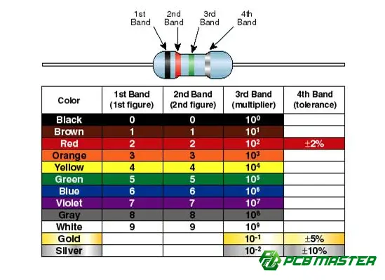
A standard four-band resistor uses:
| Band | Meaning |
|---|---|
| 1st Band | First significant digit |
| 2nd Band | Second significant digit |
| 3rd Band | Multiplier |
| 4th Band | Tolerance |
Common Resistor Color Code Table
| Color | Digit | Multiplier |
|---|---|---|
| Black | 0 | ×1 |
| Brown | 1 | ×10 |
| Red | 2 | ×100 |
| Orange | 3 | ×1,000 |
| Yellow | 4 | ×10,000 |
| Green | 5 | ×100,000 |
| Blue | 6 | ×1,000,000 |
| Violet | 7 | ×10,000,000 |
| Gray | 8 | ×100,000,000 |
| White | 9 | ×1,000,000,000 |
Tolerance colors:
| Color | Tolerance |
|---|---|
| Brown | ±1% |
| Red | ±2% |
| Gold | ±5% |
| Silver | ±10% |
Example: Identifying a 4.7kΩ Resistor
Color bands:
Yellow – Violet – Red – Gold
Calculation:
- Yellow = 4
- Violet = 7
- Red multiplier = ×100
Result:
47 × 100 = 4700Ω = 4.7kΩ
Tolerance:
Gold = ±5%
How to Choose the Right Resistor Value for PCB Design?
Resistor values are not chosen by simply matching resistance. Engineers need to consider electrical performance, manufacturing requirements and application environment.
1. Determine Required Resistance Value
The basic relationship follows Ohm’s Law:
V = I × R
Where:
- V = Voltage
- I = Current
- R = Resistance
Example:
If an LED requires 10mA current from a 5V supply:
R = (5V - LED voltage) / 0.01A
The calculated value may not exactly match a standard resistor value. Engineers normally select the closest available E-series value.
2. Consider Power Rating
A resistor must safely dissipate generated heat.
Power calculation:
P = I² × R
Common resistor power ratings:
| Power Rating | Typical Usage |
|---|---|
| 0.0625W | Small signal circuits |
| 0.125W | Compact electronics |
| 0.25W | Standard PCB applications |
| 0.5W+ | Power circuits |
Incorrect power selection can lead to overheating, reduced reliability, or component failure.
3. Evaluate Tolerance Requirements
Tolerance determines how much the actual resistance can vary.
Example:
A 1kΩ resistor with:
- ±5% tolerance: 950Ω–1050Ω
- ±1% tolerance: 990Ω–1010Ω
Precision applications require tighter tolerance components, while cost-sensitive designs may use standard ±5% parts.
Common Resistor Values Used in PCB Manufacturing
In practical PCB and PCBA production, some resistor values appear frequently because they match common circuit requirements.
| Resistance Value | Typical Function |
|---|---|
| 0Ω | Jumper, configuration selection |
| 10Ω | Signal filtering, current limiting |
| 100Ω | Signal termination, protection |
| 220Ω | LED current limiting |
| 330Ω | LED circuits |
| 1kΩ | Pull-up/pull-down circuits |
| 4.7kΩ | Sensor circuits, communication interfaces |
| 10kΩ | Logic control circuits |
| 100kΩ | Biasing and timing circuits |
Design Tip: Using standard resistor values improves component availability and reduces manufacturing delays.
Common Mistakes When Selecting Resistor Values
Choosing Non-Standard Resistance Values
It may not be easy to find a calculated value like 236Ω. For ease of sourcing you can consider a close E-series value, e.g. 240Ω.
Ignoring Temperature Effects
Resistance varies with temperature. Temperature coefficient parameters should be considered by engineers for demanding applications.
Selecting Incorrect Power Ratings
A resistor operating near its maximum power rating may experience reduced lifespan.
Overlooking PCB Assembly Requirements
Component selection must consider:
- Package size (0402, 0603, 0805, etc.)
- SMT assembly capability
- Availability
- Automated placement requirements
PCBMASTER’s Approach to Reliable Resistor Integration in PCB and PCBA Manufacturing
Being a professional PCB and PCBA manufacturer for the global electronics industries, PCBMASTER knows the component choice and production quality will directly affect the reliability of the final product.
PCBMASTER is certified to ISO 9001 quality management system, IATF 16949 automotive quality management certification, UL certification and RoHS compliance. We follow strict production standards throughout the PCB fabrication and assembly processes.
PCBMASTER offers resistor-based circuit applications:
- Professional engineering file review to identify potential design and manufacturability issues before production
- Advanced AOI inspection and multiple quality inspections to ensure accurate component placement
- SMT assembly capabilities for high-volume and precision PCB production
- Flexible PCB solutions, including rigid PCB, HDI PCB, FPC, and rigid-flex PCB manufacturing
Whether it is a basic control board or a complicated electronic system, accurate resistor selection and expert PCB fabrication will contribute to consistent product performance.
Future Trends in Resistor Selection for Modern Electronics
The resistor selection is also changing with the PCB technology as electronic devices are becoming smaller, faster and smarter.
Key trends include:
| Trend | Impact on Resistor Applications |
|---|---|
| Miniaturization | Increased adoption of smaller SMT resistor packages |
| Automotive Electrification | Higher reliability and precision requirements |
| High-Speed Communication | Greater demand for signal integrity control |
| IoT Devices | Low-power resistor solutions |
As PCB designs become increasingly complex, closer interaction between component engineers and PCB manufacturers will be required to improve electrical performance, reliability and production efficiency.
Conclusion
Standardized E-series systems using common resistor values facilitate circuit design , component procurement and PCB manufacture . Today you are aware of resistor series , color codes , tolerance and power ratings helps engineers to better component decisions .
Selecting the correct resistor value is only half of realizing reliable performance for modern electronic equipment. Professional pcb manufacturing process, quality management system & engineering support is equally crucial.
Focusing on the integration of innovative PCB manufacturing facilities and stringent quality standards, PCBMASTER supports global customers to develop dependable PCB and PCBA solutions for a variety of applications.
Tags: #ResistorValues #ESeriesResistors #PCBDesign #PCBAManufacturing #SMTAssembly #ElectronicComponents #PCBMASTER #IndustryInsights
About the Author

Carol Luo
PCB Design EngineerI'm Carol, a PCB Engineer at PCBMASTER with experience in PCB design and manufacturing engineering since 2018. I focus on translating engineering requirements into reliable PCB solutions, with expertise in stack-up design, material selection, and design-for-manufacturing (DFM). I share practical engineering insights from real-world PCB design and production experience.
Visit Carol Luo's Profile

