








Resistors in Parallel: How to Calculate Equivalent Resistance Step by Step
One of the most popular configurations in the electronic circuits is the parallel connection of the resistors. In this configuration several resistance ways can work together, sharing the same voltage. It is important to understand the behavior of these networks of resistors to correctly analyze the circuits and design reliable electronic systems .
But when there are more than 2 resistors, finding the equivalent resistance of resistors in parallel can be very confusing. In series circuits, the resistances are simply added together, but parallel circuits require a different method of calculation.
This guide contains the principles of resistors in parallel and a simple step by step method to calculate equivalent resistance. You will learn how to solve parallel resistor problems with confidence and accuracy from the basics of the formula up to common mistakes in calculation.
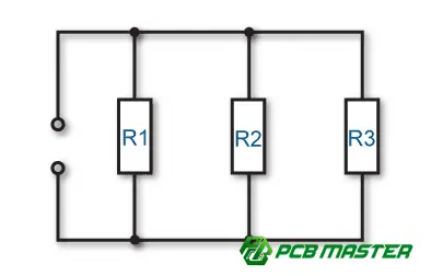
What Are Resistors in Parallel and How Do Parallel Circuits Work?
Parallel resistors are connected across the same two points in a circuit, offering multiple paths for current to flow. In a parallel resistor circuit, the voltage across each resistor is the same, but the total current is divided among the different branches.
Definition of a Parallel Resistor Circuit
A parallel resistor circuit is a configuration of a circuit in which two or more resistors are connected between the same two nodes. Since all resistors share the same beginning node and the same ending node, each resistor provides an independent electrical current path.
For example if you have three resistors in parallel , each resistor creates its own branch , between the positive and negative sides of the power source . The current can now choose to go through any of these branches , rather than being forced to choose one path .
A simple way to think about parallel resistor connections is to think of it as many roads between two cities. Each road provides an additional route for traffic to travel. Likewise, each resistor branch provides an additional path for electric current.
Engineers often use parallel resistor circuits in electronic devices to control resistance values, distribute current, and improve circuit performance.
How Voltage and Current Behave in Parallel Resistor Circuits
In a parallel resistor circuit each resistor has the same voltage across it and current splits between different resistor branches according to their resistance values.
All the resistors are connected in parallel to the same two points so they all get the same voltage from the power supply. For example if a circuit has a 12V source then all the resistors connected in parallel will have 12V across them.
However the current that flows through each resistor is different. According to Ohms Law, the lower the resistance of a resistor, the more current it will allow to pass through it, and the higher the resistance of a resistor, the less current it will allow to pass through it.
The total current in a parallel circuit is the sum of all the branch currents . For example , if we have three parallel resistors with 1A , 2A and 3A respectively , then the total circuit current will be 6A .
The property of current sharing is useful in parallel resistor networks in circuits where multiple components are to be powered from the same voltage source.
Why Parallel Resistors Reduce Equivalent Resistance
When you add resistors in parallel, you're adding more resistor branches, and that means more paths for current to flow through, making it easier for charge to flow through the circuit.
The total resistance when the resistors are connected in parallel is always less than the resistance of the smallest resistor . This is because the current does not have to go through one resistor only , but can flow through multiple branches simultaneously .
For example, one 10Ω resistor limits the current in one path. If I add another 10Ω resistor in parallel there are two paths for current and the total resistance is 5Ω.
The relation between the resistance of a branch and the total resistance is simple: the more branches in parallel, the lower the equivalent resistance will be. That is why there is a different formula for calculating parallel resistors than series resistors.
This is the starting point for calculating the equivalent resistance of resistors in parallel . This is a key component in circuit analysis and PCB design .

How Does the Resistors in Parallel Formula Calculate Equivalent Resistance?
The resistors in parallel formula is used to find the equivalent resistance of a group of resistors by combining their resistance values into one value. This one value of resistance is the way the whole group of resistors behaves electrically.
What Is the Equivalent Resistance of Parallel Resistors?
Equivalent resistance is the value of a single resistor that can replace a set of parallel resistors and have the same electrical effect in a circuit.
When several resistors are connected in parallel they behave as a single resistor network . Instead of having to analyze each resistor individually, engineers can use the equivalent resistance to simplify circuit calculations .
For example , if we have a circuit with three resistors in parallel , we can substitute them with a single resistor of a certain value in circuit analysis . The relationship between the voltage and the current in the original circuit will be the same .
For parallel resistors the equivalent resistance is always less than the resistance of any of the individual resistors in the network . This is because there are multiple paths for current to flow .
What Is the Standard Formula for Resistors in Parallel?
The formula used to calculate the equivalent resistance of two or more resistors that are in parallel is based on the reciprocal of each resistor.
For multiple resistors in parallel, the formula is:
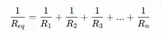
Where:
- Req = equivalent resistance of the parallel resistor network
- R1, R2, R3...Rn = individual resistor values in parallel
The calculation works as follows: First find the reciprocal of each resistance value then add all reciprocal values together, finally take the reciprocal of the result.
For example, when three resistors are connected in parallel, each resistor contributes an additional current path, so its reciprocal value is added to the total conductance of the circuit.
What Is the Formula for Two Resistors in Parallel?
Figuring out two resistors in parallel is much easier with a simple multiplication/division formula.
The formula for two resistors in parallel is :
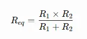
Where :
- Req = the resistance value of the equivalent resistor
- R1 = the resistance value of the first resistor
- R2 = the resistance value of the second resistor
This simple formula is more convenient when only two resistors are in parallel as there are less calculation steps involved.
For example, a 10Ω resistor and a 20Ω resistor are placed in parallel:
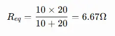
The equivalent resistance is 6.67Ω which is less than the smallest resistor value (10Ω) by the basic rule for parallel circuits.
What Is the Formula for Multiple Resistors in Parallel?
For 3 or more parallel resistors we use the standard reciprocal formula . Adding more resistors gives another path for current to flow.
The calculation method is the same regardless of the number of resistors:
- List all resistor values.
- For the resistances find the reciprocal.
- Add all the reciprocal values.
- The answer is the opposite of the final answer.
For example , if you have a circuit with three resistors ( R1 , R2 , and R3 ) in parallel , the formula would be :
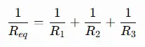
Adding more parallel branches will always decrease the total resistance , because each branch provides another path for current flow .
Why Is Equivalent Resistance Lower Than Individual Resistors?
Parallel circuits have lower equivalent resistance because the multiple resistors provide more pathways for current to flow, thereby reducing the total resistance experienced by the power source.
In a single resistor circuit there is only one path for current to travel through . In a parallel resistor network current can split up between several branches . The more paths there are for current to travel the less opposition there is to current flow .
Mathematically, the reciprocal formula results in an overall increase of the circuit conductance. Conductance and resistance are inversely related, therefore an increase in conductance results in a decrease of the equivalent resistance.
A simple rule of thumb to check your math: The equivalent resistance of resistors in parallel should always be less than the smallest resistor in the circuit.
For example if you have a parallel circuit with 10Ω, 20Ω and 50Ω resistors the equivalent resistance must be less than 10Ω. If the result is higher you should double check the formula or calculation.

How Do You Calculate Resistors in Parallel Step by Step?
To find the resistors in parallel you need to know the value of each resistor and use the proper formula for parallel resistance then summing the reciprocals and the taking the reciprocal of the sum to get the equivalent resistance.
These five steps are a simple way of finding the equivalent resistance of parallel resistors in any circuit.
Step 1: Identify All Resistor Values in the Parallel Circuit
The first step is to write down all of the resistor values that are connected in parallel and make sure that they are connected to the same two connection points.
Before beginning the calculation, identify all resistors in the parallel network. Write the value of resistance of each resistor with the correct unit (Ω, kΩ or MΩ).
For example , a parallel circuit may have :
- R1 = 10Ω
- R2 = 20Ω
- R3 = 30Ω
You now must ensure that these resistors are actually connected in parallel . Each resistor must be connected between the same two nodes , so they have the same voltage across them .
This step prevents a common mistake: using the parallel resistor formula for a circuit with series and parallel combinations.
Step 2: Apply the Parallel Resistance Formula
Use the appropriate parallel resistance formula based on the number of resistors in the circuit.
The simplified formula can be used for two resistors:
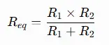
For three or more resistors, the standard reciprocal formula is required:
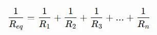
Using the appropriate formula will simplify the calculation and avoid mistakes.
For example, in a circuit with 3 resistors in parallel (10Ω , 20Ω , and 30Ω ), you have to use the multiple-resistor formula because there are more than 2 branches.
Step 3: Calculate the Reciprocal Value of Each Resistor
To find the reciprocal value of each resistor, divide 1 by the resistance.
You take the reciprocal of a resistance value:

For example:
- 1/10Ω = 0.1
- 1/20Ω = 0.05
- 1/30Ω = 0.0333
We use reciprocal values because we are dealing with parallel resistors and parallel resistors are based on conductance, which is how easily current can flow through a circuit.
The higher the conductance value , the more the circuit allows current flow through it . The equivalent resistance is thus lower .
Step 4: Add All Reciprocal Resistance Values
Add all the reciprocal values together to get the total conductance of the parallel resistor network.
When you have all the reciprocal values , add them up :
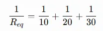
Using the example values :
0.1+0.05+0.0333=0.1833
At this point , the value you have is the combined reciprocal resistance value , not the equivalent resistance value .
It is important to keep the calculation organized because errors are often made when the reciprocal values are added in the wrong way.
Step 5: Calculate the Final Equivalent Resistance
From previous result:
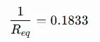
So,
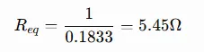
The three resistors in parallel have a total equivalent resistance of about 5.45Ω .
Finally compare the answer with the smallest resistor value. In this example the smallest resistor is 10Ω so the equivalent resistance should be less than 10Ω. The answer of 5.45Ω proves that the calculation makes sense.
By using these five steps you will have a reliable way to find the equivalent resistance of parallel resistors in electronic circuits, PCB layouts and circuit analysis applications.

What Common Mistakes Should You Avoid When Calculating Parallel Resistance?
Top 5 mistakes in parallel resistance calculations are : Summing the resistors , ignoring the last reciprocal step , confusing series and parallel , using the wrong units , and rushing to round off .
Avoid these mistakes and you will be able to correctly calculate the parallel equivalent resistance of resistors and avoid incorrect results in circuit analysis.
Adding Parallel Resistors Directly Instead of Using the Formula
You can not add parallel resistors . Series resistors have one current path , while parallel resistors have multiple current paths .
A common mistake is to calculate parallel resistance as though it were a series circuit:
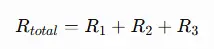
This is only true for resistors in series . In a parallel circuit , the more resistor branches you add , the less total resistance you have ( current has more paths to flow through ) .
For example, two 10Ω resistors in series equal 20Ω, but two 10Ω resistors in parallel equal 5Ω.
Before calculating the equivalent resistance, always verify the type of connection of the circuit and use the correct resistors in parallel formula.
Forgetting the Final Reciprocal Calculation
You have to do one more reciprocal step after adding up the reciprocal resistance values to get the final equivalent resistance.
The standard formula for parallel resistance is :
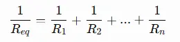
A common mistake is to stop at this stage and take the result as the equivalent resistance . This is not the equivalent resistance ; it is the reciprocal of the equivalent resistance .
For example:
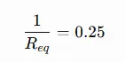
The correct final step is:
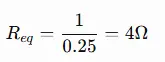
Remembering the final reciprocal calculation is essential to obtaining the correct parallel resistance value.
Mixing Series and Parallel Resistor Connections
For mixed circuits of series and parallel resistors, you need to calculate each portion separately, then calculate the total resistance.
In actual electronic circuits, the resistors are not all in parallel or all in series . Frequently there are mixed resistor networks . The components of a mixed resistor network are partly series and partly parallel .
For example, if you have two resistors in parallel and another resistor in series with that group, calculate the parallel group first and then add the series resistor value.
The right way is:
- Find separate series and parallel parts.
- Calculate each section separately.
- Step by step combine the results.
If you use the wrong formula for a mixed circuit you can get a totally wrong answer for the equivalent resistance.
Using Incorrect Resistance Units During Calculation
To prevent wrong equivalent resistance results, all resistance values must be in the same units before calculation.
Resistance values may be written in:
- Ohms (Ω)
- Kilohms (kΩ)
- Megohms (MΩ)
Mixing these units without conversion can create large calculation errors.
For example:
- 10Ω
- 2kΩ
cannot be used directly together. First the values need to be converted to the same unit :
2kΩ=2000Ω
And then the parallel resistance formula can be correctly applied .
An easy way to avoid wrong results in circuit analysis is to check units before calculation.
Rounding Values Too Early
Prematurely rounding reciprocal values can affect calculation accuracy and thus an incorrect final resistance value.
When converting resistances into reciprocal form, you will often end up with decimal values for parallel resistors. If you round these numbers too early, this can cause significant errors when you have more than one resistor.
For example, rather than rounding:
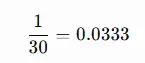
to
0.03
keep more decimal places until the last step of the calculation.
It is good practice to keep at least three or four decimal places in intermediate calculations and round off the final result of equivalent resistance .
Even slight changes in the resistance can change the current flow and operation of a circuit. This is especially true in electronics and PCB layout.
How Are Resistors in Parallel Different from Resistors in Series?
Parallel vs Series Resistors Parallel and series resistors differ in how resistance is calculated, voltage and current division, and their application in electronic circuits. Resistors in parallel offer multiple paths for current, whereas resistors in series offer a single path for current.
It is important that engineers understand the difference between these two resistor configurations to select the proper method of circuit design and correctly calculate the equivalent resistance.
Difference in Equivalent Resistance Calculation
Resistors in series are just added together , but resistors in parallel need a reciprocal formula to calculate the equivalent resistance .
The equivalent resistance for resistors in series is :
Req=R1+R2+R3+...+Rn
Each resistor adds more opposition to the flow of current because the current must go through each resistor along the same path.
The formula for the equivalent resistance in resistors in parallel is :
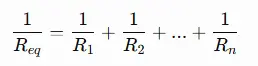
Parallel circuits provide many paths that current can take and so the equivalent resistance will always be less than the smallest resistor in the system.
This is the difference. This is why engineers need to know if resistors are in series or parallel before calculating the resistance.
- Two 10Ω resistors in a series circuit:
10Ω+10Ω=20Ω
- Two 10Ω resistors in a parallel circuit:
Req=5Ω
Difference in Voltage and Current Distribution
In a series circuit the current is the same through all the resistors and the voltage is divided. In a parallel circuit the voltage is the same across all the resistors and the current is divided.
Series resistor circuits:
- The same current flows through all resistors
- The resistors are in series across the whole supply voltage.
- The higher the resistance, the greater the voltage drop.
For example in a series circuit with two resistors the current through both resistors is the same . However each resistor uses up some of the available voltage .
Resistors in Parallel :
- Same voltage across each resistor.
- Total current is split over different branches.
- Higher current passes through lower resistance branches.
So for example in a 12V parallel circuit, all the resistor branches have 12V across them, but each branch might have different current through it depending on its resistance .
Comparison Table
The main difference between series and parallel resistors is in their treatment of resistance, voltage and current.
| Feature | Resistors in Series | Resistors in Parallel |
|---|---|---|
| Current path | One path | Multiple paths |
| Resistance calculation | Add all resistance values | Use reciprocal resistance formula |
| Equivalent resistance | Higher than individual resistors | Lower than the smallest resistor |
| Current behavior | Same current through all resistors | Current divides between branches |
| Voltage behavior | Voltage is divided | Same voltage across each resistor |
| Adding more resistors | Increases total resistance | Decreases total resistance |
| Common use | Voltage division, current limiting | Current sharing, resistance adjustment |
When Should Parallel or Series Resistors Be Used?
Series resistors are used when designers want to increase resistance or control voltage. Parallel resistors are used when designers want to decrease resistance or share current.
Common Applications of series resistors:
- Voltage division: A certain level of voltage can be generated using two or more series resistors.
- Current limiting:Series resistors are often used to limit current through LEDs and other components.
- Signal control:Series resistors can be used to reduce signal level or control the operation of a circuit.
Common uses of parallel resistors are:
- Resistance adjustment: The resistance of a resistor can be changed by connecting a resistor in parallel.
- Current sharing : Several resistors can share power , and reduce stresses on individual components .
- Power handling:Several resistors in parallel can share the heat and increase the total power handling.
For example, in PCB design, engineers may use two resistors in parallel to achieve a certain resistance value as well as to improve power distribution. On the other hand, a series resistor may be chosen when its main purpose is to limit current through a sensitive component.
The current flows differently in a parallel resistor configuration . The choice of either parallel or series depends on the resistance needed , how much current needs to flow , the voltage needed , and the overall performance of the circuit .

Conclusion
One of the most important skills in the analysis and design of electronic circuits is the calculation of resistors in parallel. When you learn how to recognize the resistor configuration, use the correct formula and follow a step-by-step calculation process, you can accurately calculate the equivalent resistance and avoid common mistakes in your calculations.
Furthermore, the ability to discriminate between parallel and series resistor setups enables engineers to intentionally design circuits for altering resistance values, regulating current flow, or enhancing power delivery.
PCBMASTER provides professional support for PCB design and manufacturing . PCBMASTER delivers dependable PCB and electronic manufacturing services, assisting engineers in transforming their circuit concepts into high-quality products. Leveraging extensive experience in PCB manufacturing and cutting-edge manufacturing facilities, PCBMASTER guarantees that each design adheres to performance and reliability criteria.
FAQ: Common Questions About Resistors in Parallel
Can resistors with different resistance values be connected in parallel?
Yes, resistors of different resistance values can be connected in parallel. In fact, parallel resistor circuits often have resistors of different values to achieve a desired equivalent resistance or to improve the circuit performance.
When you hook up resistors with different values in parallel , they all have the same voltage across them but the current through each branch will be different . The branches with lower resistance allow more current through while the branches with higher resistance allow less current through .
For example, you can connect a 10Ω resistor and a 100Ω resistor in parallel. The equivalent resistance will be less than 10Ω because both resistors provide additional paths for the current to flow.
What happens to equivalent resistance when more resistors are added in parallel?
The more resistors you add in parallel , the lower the equivalent resistance gets . Each resistor added in parallel adds another path for current to flow through , so there is less overall resistance to current flow .
For example, if you add a second resistor in parallel to an existing resistor, the overall resistance is lowered because the circuit now has two paths for current instead of one.
However, the reduction becomes smaller with the addition of more resistors . The effect of the first few parallel resistors on equivalent resistance is larger while additional resistors produce smaller changes .
Why is the total resistance always lower in a parallel circuit?
In a parallel circuit the total resistance is less because there are lots of different paths for the current to flow through at the same time.
In a single resistor circuit there is only one path for current to flow through . The more branches you add in parallel , the easier it is for current to flow through the circuit .
This is why the equivalent resistance of parallel resistors is always less than the smallest individual resistor value. If the answer you get is greater than the smallest resistor in the network then the answer is probably wrong.
Does resistor tolerance affect the equivalent resistance of parallel resistors?
Yes , the resistor tolerance can affect the actual equivalent resistance of a parallel resistor network .
Tolerance of a resistor is a measure of how much the actual resistance value can vary from the marked value . For example , a 100Ω resistor with a tolerance of ± 5 % , may have an actual resistance between 95Ω and 105Ω .
But when you have many resistors in parallel, these tiny differences can make a difference in the end result equivalent resistance. When designing circuits that need to be precise, engineers factor in resistor tolerance to make sure the circuit works as expected.
About the Author

Carol Luo
PCB Design EngineerI'm Carol, a PCB Engineer at PCBMASTER with experience in PCB design and manufacturing engineering since 2018. I focus on translating engineering requirements into reliable PCB solutions, with expertise in stack-up design, material selection, and design-for-manufacturing (DFM). I share practical engineering insights from real-world PCB design and production experience.
Visit Carol Luo's Profile

