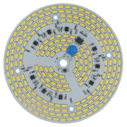
PCBMASTER will take you to understand the seven core principles of PCB LED design and three future trends.
Author: Jack Wang
In 2023, the global LED lighting market exceeded $80 billion. However, 37% of engineers still encounter heat dissipation failure problems during the PCB design phase. This article distills million - dollar practical experience to help you avoid 90% of design pitfalls.

I. Physical Characteristics of LEDs and the Underlying Logic of Design
1. The essence of optoelectronic conversion: The electron - hole recombination efficiency of GaN - based LEDs directly affects the quality of blue light (wavelength 450 - 470nm).
2. Misconceptions in white light realization: An error in the thickness of the phosphor coating exceeding ±5μm will cause a color temperature shift of >200K.
3. Material selection formula: Thermal expansion coefficient CTE (ppm/℃) = CTE of the substrate - CTE of the LED chip ≤ 5.
II. The Golden Triangle of Design: Collaborative Control of Heat, Electricity, and Light
1.Five elements of thermal management:
①Substrate selection comparison table (Comparison of thermal conductivities of FR4, aluminum substrate, and ceramic substrate).
②Calculation formula for copper layer thickness and heat dissipation area: Q = λAΔT/d .
③Design specifications for thermal vias array (hole diameter 0.3mm, pitch 1.2mm).
④Misconceptions in heat sink selection: Matching curve of fin height and air velocity
⑤Practical measurement case: Optimization path to reduce the temperature rise of a 5W LED module from 78℃ to 45℃
Substrate Selection Comparison Table (from the perspective of thermal management)
Comparison Dimension | FR4 Epoxy Resin Substrate | Aluminum Substrate (MCPCB) | Ceramic Substrate (Al₂O₃/AlN) |
Thermal Conductivity | 0.3 - 0.4 W/m·K | 1.0 - 2.2 W/m·K | 24 - 180 W/m·K |
Thermal Expansion Coefficient (CTE) | 14 - 17 ppm/℃ | 22 - 24 ppm/℃ | 4.5 - 7.5 ppm/℃ |
Temperature Resistance Limit | 130℃ | 150℃ | 850℃(AlN)/500℃(Al₂O₃) |
Insulation Layer Structure | All - material insulation | Thermal insulation layer (75 - 150μm) | Self - insulation |
Processing Cost | $0.11 - 0.17 usd/cm² | $0.35 - $0.56 usd/cm² | $2.08 - $4.2 usd/cm² |
Applicable Power Density | <3W/cm² | 3 - 10W/cm² | >10W/cm² |
Typical Failure Modes | Delamination (>100℃ cycles) | Carbonization of the insulation layer (>5kV) | Mechanical brittle fracture (impact test) |
2. Three principles of circuit design
①Current equalization schemes: Comparison of dynamic current - sharing circuit topologies (series/parallel/matrix).
②Control of line losses: The latest IPC standards for copper foil thickness and current - carrying capacity.
③Protection circuit configuration table (TVS selection parameter comparison).
3.Ironclad rules of optical layout:
①Calculation formula for LED spacing: D = √(A/N) (A is the lighting area, N is the number of LEDs)
②The golden ratio of the light - mixing distance to the diffuser plate thickness
③Case analysis: How to achieve an illumination uniformity of >95% in medical operating lights
III. Devilish Details in the Production Process
Welding process window:The impact of the reflow soldering temperature curve on LED light decay (peak temperature 245±3℃).
Anti - sulfurization process: Selection criteria for conformal coating (meeting MIL - I - 46058C certification).
Testing and verification system:
① Photobiological safety testing (IEC 62471)
②Accelerated aging test plan (light decay curve at 85℃/85%RH environment). Selection guide for optical testing equipment (integrating sphere vs. goniophotometer)
③ Environment Selection guide for optical testing equipment (integrating sphere vs. goniophotometer)

IV. Three Future Technological Breakthroughs
1. New heat - dissipation materials: The mass - production process of graphene - composite substrates (with a predicted 40% cost reduction in 2025).
2. Intelligent integration solutions: The integrated design of COB packaging and driver ICs.
3. Breakthroughs in environmental - friendly technologies: Reliability verification data of lead - free soldering processes (results of 3000 thermal cycle tests).

Example: A certain vehicle - mounted LED project increased the Mean Time Between Failures (MTBF) from 5,000 hours to 30,000 hours by applying the above - mentioned solutions. Remember: Excellent design = 80% understanding of physics + 15% engineering experience + 5% process innovation. which will help you quickly locate 90% of heat - dissipation problems.![]()
If you would like to learn more knowledge in this area, please feel free to contact us at www.pcbmaster.com. PCBMASTER is willing to share more topics related to this field with you at any time.
Author: Jack Wang