Redefining the Heat Dissipation Boundaries of Circuit Boards
In the thermal failure accidents of new energy vehicle electronic control systems, engineers discovered that the thermal resistance of traditional FR-4 substrates (3.5 - 4.0°C-in²/W) cannot meet the heat dissipation requirements of 800A IGBT modules. This industry "pain point" has directly spurred the leapfrog development of Metal Core PCB (Metal Core PCB or Metal base PCB, MCPCB/MBPCB) technology. According to Prismark's statistics, the global metal substrate market size reached $1.87 billion in 2023, with a stable compound annual growth rate of 11.2%, making it the fastest - growing segment in the high - end electronics manufacturing field.
I. Metal Core PCB Technology Map

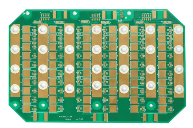
1.1 Structural Deconstruction and Material Revolution
①The typical sandwich structure includes:
Metal substrates (0.8 - 5.0mm): 6061 aluminum alloy (thermal conductivity 180W/mK), C1100 copper (398W/mK), Invar (1.5W/mK)
② Insulating layers (50 - 200μm): High - thermal - conductivity epoxy resin (1.5 - 3.0W/mK), polyimide (0.2W/mK), ceramic fillers (AlN powder)
Circuit layers (1 - 10oz copper thickness): A special lamination process is used to achieve an interfacial thermal resistance of <0.05°C/W
1.2 Comparison of Four Substrate Types
Parameters | Aluminum Substrate | Copper Substrate | Iron Substrate | Composite Substrate |
Thermal Conductivity (W/mK) | 180 - 220 | 380 - 400 | 30 - 50 | 150 - 180 |
CTE (ppm/°C) | 23.6 | 17.0 | 11.7 | 14 - 18 |
Cost Index | 1.0 | 3.2 | 0.8 | 2.5 |
Typical Applications | LED Lighting | Automotive Electronics | Precision Instruments | Aerospace |
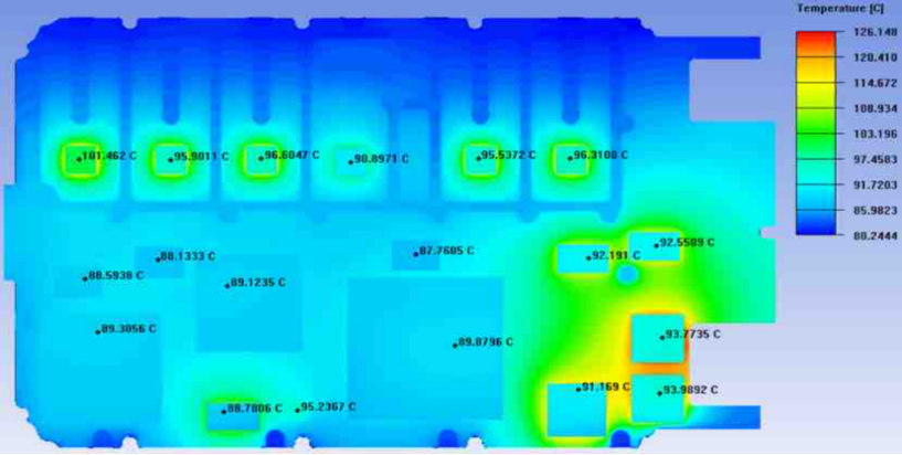
II. Key Performance Breakthrough
2.1 Leap in Thermal Management Dimension

① Optimization of the heat conduction path: The copper substrate can reduce the thermal resistance to 0.15°C/W (traditional substrates > 2.5°C/W)
② Improvement of the thermal cycle life: In the - 40°C to 150°C cycle test, the solder joint life of the aluminum substrate is extended by more than 5 times
Breakthrough in temperature uniformity: The surface temperature difference of a 10×10cm copper substrate is <3°C (under the same power density, the temperature difference of FR-4 is >25°C)
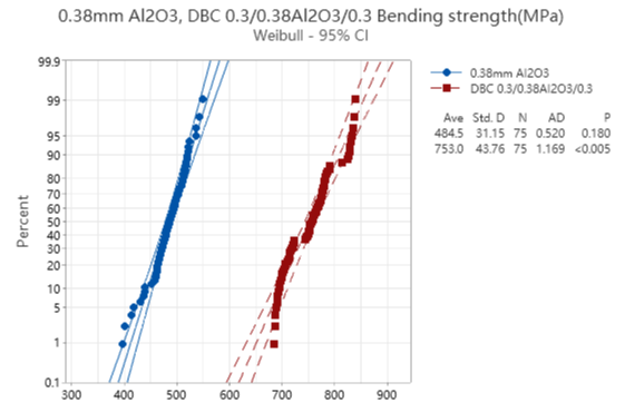
2.2 Reconstruction of Mechanical Properties

①Flexural strength: A 2.0mm aluminum substrate reaches 300MPa, which is 4 times that of FR-4
②Dimensional stability: CTE matches chip - level packaging (<5ppm difference)
Electromagnetic shielding: The shielding effectiveness of the copper substrate at 1GHz reaches 65dB
III. Engineering Application Decision Tree

3.1 Analysis of the Selection Decision - Making Logic
The selection of Metal Core PCBs needs to follow a three - level decision - making logic of "power density - thermal stress - mechanical stress":
① First - level: Power density determination
When the power density > 0.5W/cm² (such as high - power LEDs, IGBT driver modules), a metal substrate solution must be adopted.
When the power density ≤ 0.5W/cm² (such as ordinary control circuits), proceed to the next - level determination.
② Second - level: Thermal stress analysis (for high - power scenarios)
If the instantaneous peak temperature > 125°C (such as electric vehicle motor controllers):
Give priority to choosing a copper substrate (thermal conductivity ≥ 380W/mK) to ensure that the thermal resistance is <0.2°C/W.
If the instantaneous peak temperature ≤ 125°C (such as industrial power modules):
Choose an aluminum substrate (thermal conductivity ≥ 180W/mK) to balance cost and heat dissipation requirements.
③ Third - level: Mechanical stress assessment (for low - power scenarios)
In a vibration/impact environment (such as rail transit equipment, heavy machinery):
Select an iron substrate (flexural strength ≥ 450MPa) and utilize its low CTE characteristic (11.7ppm/°C) to match the metal housing.
In a conventional static environment:
Maintain the traditional FR-4 substrate solution to control costs.
3.2 Golden Rules for Design
① Heat channel design: Power components must be in direct contact with the metal substrate, and the diameter of the heat - conducting holes needs to be >0.3mm.
② Lamination process control: The thickness tolerance of the insulating layer needs to be <±8%, and the peel strength > 1.2N/mm.
③ Drilling parameter optimization: For hard aluminum alloy substrates, the recommended drilling speed is 120 - 150m/min, and the feed rate is 0.03mm/rev.
IV. Frontier Application Case Library
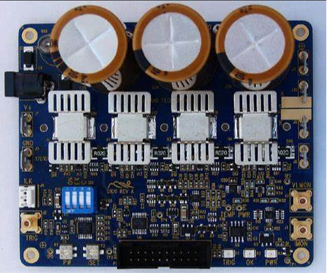
4.1 Tesla 4680 Battery BMS System

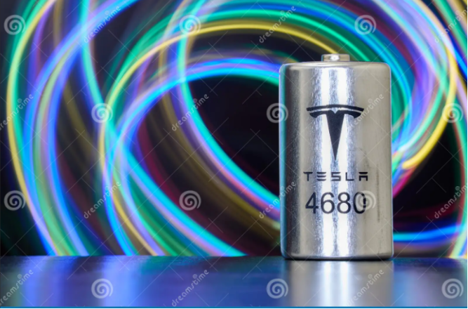
It adopts a three - layer copper substrate stacking structure:
①Substrate thickness: 2.0mm OFC copper
② Insulating layer: 125μm AlN - filled resin
③ It realizes a 96 - channel temperature acquisition system, and the thermal gradient is controlled within ±1.5°C.
4.2 Industrial Laser Driver Module

① Substrate material: 3mm copper - molybdenum alloy (thermal conductivity 220W/mK, CTE 7.2ppm/°C)
② Thermal cycle test: After 3000 cycles, the resistance drift is <0.5%
③ Power density: It breaks through the industry limit of 82W/cm²
V. Technology Evolution Roadmap

1.Nanoscale interface engineering: The graphene coating reduces the interfacial thermal resistance to 0.01°C/W.
2.Heterogeneous metal composites: Copper - aluminum composite substrates achieve directional heat conduction (380W/mK longitudinally, <50W/mK laterally).
3.Intelligent heat sink technology: The integration of phase - change materials (PCM) and Metal substrates increases the thermal buffer capacity by 400%.
Conclusion: Redefining the Thermal Boundaries of Electronic Systems
When a leading photovoltaic inverter manufacturer optimized the thickness of the aluminum substrate from 3.0mm to 1.6mm, the system power density increased by 37%, and the MTBF (Mean Time Between Failures) jumped from 50,000 hours to 80,000 hours. This verifies that Metal Core PCBs are not only heat dissipation components but also the core carriers for reconstructing the reliability of electronic systems. With the popularization of 5G millimeter - wave and silicon carbide devices, metal substrates are breaking through traditional cognitive boundaries and developing towards multi - functional integration.
(Data sources of this article: IPC - 6012D standard, Bergquist technical white paper, test report of Nippon Chemical Industrial Co., Ltd.)
Comprehensive Analysis of Metal Core PCB Technology From Material Characteristics to Industry Application Practices
Evolution of Metal Core PCB Technology and Market Transformation Key Drivers of a Trillion-Dollar Market
Author:Jack Wang