PCBMASTER shares with you the practical design of flexible-rigid printed circuit boards in medical devices!
2025-03-03 00:00:00
Author: Jack Wang
Industry Demand Case Study:
Implantable devices like pacemakers require PCBs to withstand >500,000 bends over 10 years with a thickness ≤0.4mm. Traditional designs showed a 23% failure rate, making rigid-flex PCBs the breakthrough solution.

Key Technological Breakthroughs
1. Material System Innovation
① Substrate Selection:
Polyimide (PI) films offer 200× better bend resistance than FR-4 but cost 5× more. A balanced approach: Use PI (25μm thick) in bending zones and FR-4 in rigid areas.
② Adhesive Revolution:
Acrylic adhesive (300% elongation) outperforms epoxy resin (5% elongation) for dynamic bending. A glucose monitor project demonstrated a bend lifespan increase from 20,000 to 300,000 cycles.
2. Bending Zone Design Guidelines
Minimum Bend Radius:
Formula: R = 100 × Copper Thickness (mm). Example: 35μm copper thickness → R = 3.5mm.
Trace Layout Rules:
→ No vias allowed in bending areas
→ Traces angled at 45° to bending direction reduce stress concentration by 60%
→ Grid-pattern copper etching improves flexibility by 3×
3. Reliability Validation Methods
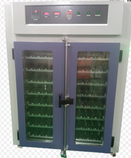
① Accelerated Aging Test:
1,000 hours at 85°C/85% RH environment, impedance variation must remain <5%.
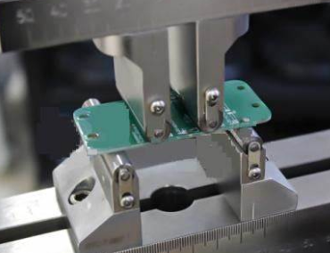
② Mechanical Fatigue Test:
Simulate human motion with servo motors (2Hz frequency, ±15° amplitude). Continuous 30-day testing with no fractures.
Typical Application Case

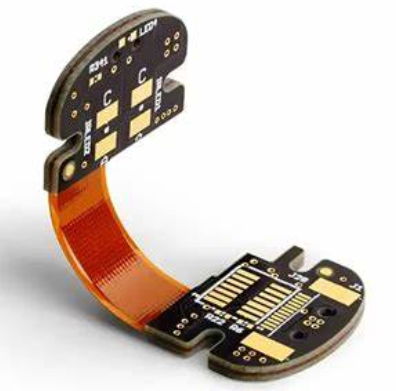
A neurostimulator using 6-layer rigid-flex design:
Rigid zones: 4-layer FR-4 for MCU and power modules
Flexible zones: 2-layer PI film for electrode array connections
Results: 0.35mm thickness, ISO 13485 certification, and 800,000-cycle bend lifespan.
If you want to know more, please feel free to contact us at www.pcbmaster.com
Author: Jack Wang
Share To
Previous:PCBMASTER shares with you how to prevent signal integrity issues in high - frequency PCB design.
Next:PCBMASTER will guide you to understand how to achieve a soldering yield rate of 99.99% in PCBA assembly.
Finished reading
Feedback / Message
NEWS
Technical Sharing
All News
Member Notice
Media Report
Industry News
PCBMaster Process
Tech Trend
Circuit Diagram
Tech Research
Solution Design
Types of PCBs
PCB Materials
PCB Design and Manufacturing
Ceramic Base PCB
Flexible PCB
HDI PCB(High - Density Interconnect PCB)
High frequency PCB
High multilayer PCB
High Speed PCB
Metal Base PCB
Mini-LED pcb
Rigid-Flex Board
Special PCB
Contact Us
Skype
service@pcbmaster.com